Dynamic frame rates can improve display panel performance
The desire for ever higher image quality has seen frame rates in high-end televisions increase to 240 frames per second (fps) simply to ensure that the fast moving action in sports programs or movies does not suffer from smearing or multiple images. Display panels for PCs similarly need to support high frame rates for gaming and video applications.
The downside of such high frame rates is inevitably increased power consumption and yet not every application or type of content needs these higher rates. In many cases, a 30Hz refresh rate will be quite sufficient with no noticeable loss of quality. A solution to this dilemma is to dynamically control the frame rate, but to achieve this in real-time requires a special circuit to adjust the pixel common voltage of the display panel to both ensure flicker-free operation with no impact on display lifetime.
Operating a display panel at higher frame rates means that it has to execute multiple image generation refresh cycles within the same time period as for a single refresh cycle at the slower rate. Aside from the higher power consumption incurred in line-powered displays, these higher frame rates will have a major impact on the run-time of mobile platforms such as a notebook PC.
Adaptive display
Future display panels will adopt a technique that adaptively adjusts frame rate based on the content being displayed and the dynamic requirements of the image. This provides an alternative between the two extremes of low rate/low power and high rate/high power. For spreadsheets or word processing, a frame refresh rate below 30Hz is fast enough, while the same display panel may be set to run at a 240Hz frame rate when displaying fast-motion game scenes.
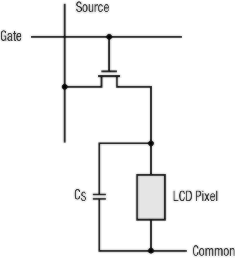
However, there are practical problems associated with increasing the frame with the typical liquid crystal or organic display (LCD or OLED) panel, as their optimum electrical operating point may change as the frame rate is varied, due to the physics of their technology and manufacturing issues. These displays use a thin-film transistor (TFT) backplane and turn these TFT devices on and off to control each pixel (see Figure 1).
Click image to enlarge
Figure 1. A simplified schematic of a TFT LCD pixel element
The TFT gate voltage is applied to a specific row of a panel, allowing the flow of current from the source voltage for the relevant column, thereby determining the pixel’s light-transparency by adjusting the potential across the the associated capacitor using an indium tin oxide (ITO) electrode, which is a semi-transparent metal layer of the display.
In typical TFT panels for TVs, where sizes span 30 to 80 inches, the source voltage can range from 0 to 24 V. As the panel size grows, the maximum source voltage also must increase as the drive-current requirement increases. The bottom connection of the pixel is usually connected to the backplane; this node voltage is called the common voltage or VCOM and should be maintained at a single potential across the entire panel area.
In order to prolong the life of a panel as well as not have a flicker problem, VCOM is typically established at about the mid-point between zero and the maximum source voltage level, equivalent to about one half of analog supply, AVDD. (Note that the common voltage VCOM is a true “common” and is not a "ground.")
Little-known TFT characteristic is key
Since the TFT backplane is fabricated by large-area thin-film deposition, the optimal value of the VCOM voltage will differ from panel to panel due to manufacturing variations, even within a single production line. It may also vary within a single panel if the size of the panel is large enough. As a result, the last inspection point of a panel module assembly is to perform a display quality test, which involves factory calibration and adjustment of the optimum VCOM voltage setting for each panel.
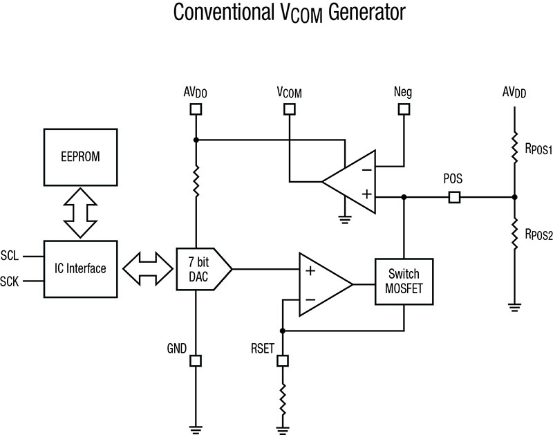
With these panels, it is important to manage VCOM to be uniform across the panel as well as over the transient period as the pixel information changes. In most panels, this is done by using between one and 12 channels of operational amplifiers, often called VCOM buffers, linked to the digital/analog converter (DAC) outputs of digital potentiometers used for storing factory-set voltage levels, as in Figure 2.
Click image to enlarge
Figure 2. Typical VCOM generator used today consists of a non-volatile memory, DAC and buffer amplifier
The situation is likely to become more complicated as displays move toward variable frame-rate (refresh rate) operation for many applications. In this scenario, the PC would display images of a spreadsheet or word-processing application at a slow 30 frames/sec, while shifting to a much-higher rate, up to 250 frames/sec, for the fast-moving motion image of a high-end game.
Variable frame-rate implementation challenges standard design
The relatively new concept of ‘adaptive sync’ format demands wide-ranging variable frame rates from a stand-alone monitor or laptop display. Varying the frame rate requires real-time adjustment of VCOM in order to avoid any flickering resulting from an initial, non-ideal VCOM setting, as the ideal VCOM level changes with the frame rate.
In the conventional panel, it would be acceptable to manage and minimize the flicker level with a single fixed VCOM value because the range of vertical frequencies from the GPU (graphics processing unit) is relatively narrow. Therefore, it is sufficient for the panel to have a single optimized VCOM level setting, and to ship it pre-set with this value. The average voltage level between odd and even frames would not see a big difference with just one fixed VCOM level that is calibrated for the center frame rate at which the panel is operating, as in Figure 3.
_CurrentTypRefreshTime.jpg)
Clcik image to enlarge
Figure 3a. Fixed refresh rate and discharge time provides potential level for odd and even frames managed by a single VCOM level
_AreaA=AreaB.jpg)
Figure 3b. Fixed refresh rate and discharge time provides potential level for odd and even frames managed by a single VCOM level
However, for variable frame-rate panels with free sync or adaptive sync, it is difficult to optimize flicker level with a single, fixed VCOM value because the variable range of vertical frequencies is much wider than it is with a conventional fixed frame rate. The variations in the discharge time span will be very high, which will aggravate the flicker problem if the VCOM voltage is pre-set and fixed (see Figure 4).
_NewFreeSyncRefreshTime.jpg)
Click image to enlarge
Figure 4a. Widely varying refresh rate results in varying discharge time and charge imbalance without adjusting the VCOM level to another level
_AreaA=AreaB2.jpg)
Click image top enlarge
Figure 4b. Widely varying refresh rate results in varying discharge time and charge imbalance without adjusting the VCOM level to another level
For example, the ratio of Area A to Area B will become very different as the refresh-time period changes significantly from the original frame rate. As the refresh period becomes longer, the optimum VCOM level will changes from VCOM1 to a new value, VCOM2. Without adjusting the VCOM level accordingly, the ratio of area A’ and Area B’ deviates from its usual value of ~1.0 as the discharge time increases.
Variable VCOM level generator (VVLG) approach
The conventional VCOM generator of Figure 2 consists of a digital voltage reference (DVR) block, an I2C interface, EEPROM and an operational amplifier. The VCOM level is set using an I2C interface and is stored in the EEPROM. This level is not changed until the user writes a new VCOM value. With this configuration, it is not practical to execute a VCOM level change "on-the-fly" as the frame rate changes from 30Hz to 90Hz, for example.
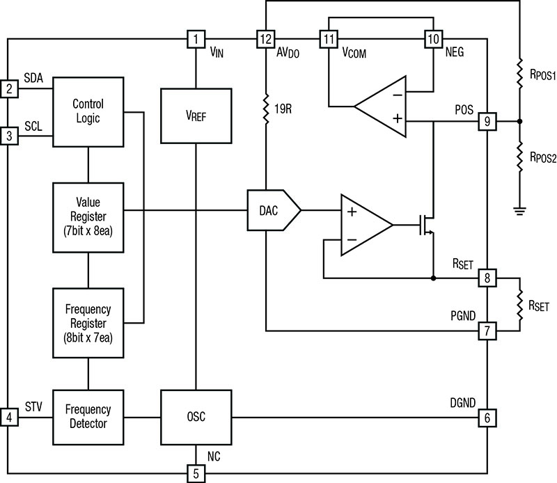
The solution is a variable VCOM reference that can adjust its value when a different frame rate is applied to the panel, as determined by the displayed-image requirements. For example, an IC that implements this new approach is the IML7918 Variable VCOM Level Generator (VVLG) from Exar Corp (see Figure 5).
Click image to enlarge
Figure 5. Block diagram of IML7918, a variable VCOM generator, capable of adjusting the VCOM level for varying refresh rates for an adaptive/free sync display panel
The concept of the VVLG is to provide a variable VCOM level, done either self-adaptively for different vertical frequencies or by an external control signal. This minimizes the perceived flicker level as the adaptively changing VCOM level minimizes the difference between Area A and Area B. When the GPU generates different vertical frequencies, the VCOM level will be also adjusted and changed to maintain balanced areas (Area A = Area B).
To address the VCOM level-adjustment requirement for an adaptive-sync display panel, a VCOM generator with multiple registers and non-volatile memory (NVM) banks corresponding to varying values of panel frame rate is needed. The factory can set optimum VCOM values for various frame rates for the panel and this device generates the VCOM output required by a timing-controller chip. For example, these can be pre-set values for 20Hz, 40Hz and higher, up to 240Hz refresh rates.
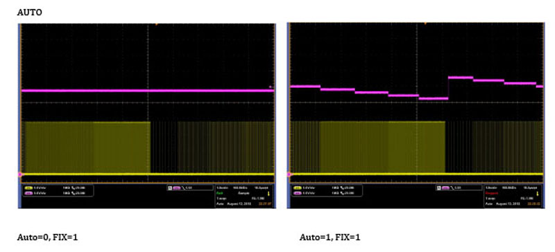
Another way of adjusting the output VCOM level is by using a frequency detector built into the IC. The counter measures the frame rate by monitoring the vertical-start (STV) signal, and adjusting the VCOM output to the correct level. Eight different VCOM values can be stored in the device and, after it determines the frequency, the IC will automatically produce the VCOM value that is best suited to making Area A’ and Area B’ equal and hence minimize flicker.
To detect and measure STV accurately, the device includes an accurately trimmed oscillator. Figure 6 shows how the change in VCOM output level is sensed by the IC's monitoring of the STV signal from the timing controller when the frame rate changes. The yellow shade difference at the bottom of the oscilloscope image represents frame-rate change and the red trace shows the VCOM output level. In Figure 6a (left) this function is disabled, while Figure 6b (right) shows the controlled change of VCOM that results from enabling this sensing function. Various VCOM levels for different frame rates are calibrated at the factory for high-performance display panels.
Click image to enlarge
Figure 6a/b. Picture of a scope measurement demonstrating a unchanging VCOM (conventional setting, left) and adjusting VCOM output using IML7918 (adaptive sync VCOM level, right). The difference in the density of the yellow shaded area is an indication of the refresh rate change and the purple line is the VCOM output generated by the chip.
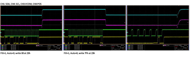
Another way of adjusting the optimum VCOM level is by supplying a control signal directly to the device via the I2C port, as in Figure 7. As scope Channels 1 and Channel 4 deliver the I2C control signal, the Channel 3 VCOM level adjusts to the desired value for the given frame rate.
Click image to enlarge
Figure 7. Demonstration of I2C controlled change of VCOM level: The bottom two channels in yellow and green are I2C SDA and SCL, respectively and Channel 3 in purple is the correspondingly-adjusted VCOM output level change.
Looking forward
“Adaptive sync” or “free sync” panels represent the next generation of displays and their controllers will have the capability for flexibly adjusting frame rate to match image quality requirements. As a consequence, it will be necessary to adjust and optimize the panel's VCOM voltage levels for a given frame rate. Otherwise, unavoidable and irritating flicker-noise will be apparent in such displays.
At present, there are no panel vendors offering a display with a robust frame-rate changing capability. While some experts say the higher frame rate is unnoticeable and therefore does not offer not a real benefit, serious display users (such as gamers) can see the difference, and it is very likely that some display vendors will try to support their needs. Devices such as the Exar IML7918 variable VCOM generator enables this upgrade, as it eliminates flicker noise by adjusting the VCOM level during frame-rate transitions.