Battery Management Accuracy Strengthens Humanoid Robot Reliability
In humanoid robotics, battery management is no longer a standalone electrical function; it is a system-level enabler of motion, stability, and reliability
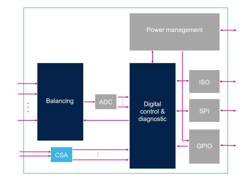
Figure 1: Simplified block diagram for the L99BM114 BMS
Humanoid robots are redefining power-density constraints. To preserve agility and reduce structural inertia, designers typically place the battery pack deep within the torso or pelvis. This compact architecture means the energy-storage system must operate inside a sealed enclosure, often alongside high-performance processors and without the benefit of airflow.
Unlike electric vehicles, which generally draw current in a more predictable manner, humanoid robots generate highly dynamic load profiles. Walking, balancing, lifting, and recovering from disturbances all produce rapid current transients. In this environment, conventional battery monitoring is often not enough.
To support stable control, the battery management system (BMS) must deliver fast, accurate telemetry that can be used directly by lower-level control loops. When voltage and current sensing are not properly synchronized, the resulting timing mismatch can introduce estimation errors that degrade control performance. In a humanoid robot, this can translate into reduced stiffness, overshoot, or even balance instability.
Traditional architectures often separate cell-voltage sensing from current measurement, using different components and communication paths. That separation can introduce timing delays and reduce the quality of dynamic state estimation. A more effective approach is to integrate voltage monitoring and current sensing on a single monolithic device.
Battery Sensing Architectures
Humanoid robot control systems rely on continuous torque adjustment through impedance-control loops to maintain balance and follow the desired motion trajectory. The stiffness of each joint depends directly on the accuracy and timing of those loops.
Motor torque capability is constrained by the DC bus voltage. As load current increases, the battery voltage drops according to the pack’s dynamic internal resistance. If the controller does not estimate this voltage drop accurately, it may issue suboptimal commands, leading to current saturation and reduced joint stiffness. This can result in overshoot, loss of trajectory accuracy, or instability.
These errors are often amplified in split-chip sensing architectures, where voltage and current are measured by separate ICs operating in different clock domains. Asynchronous sampling introduces timing mismatches that make it harder to reconstruct the true dynamic behavior of the battery. Under inverter switching noise, these mismatches can also degrade measurement quality.
A unified, single-chip architecture avoids this issue by synchronizing voltage and current conversion in hardware. When both channels are locked to the same master clock, the system can estimate dynamic cell impedance more accurately and provide the controller with coherent, real-time telemetry.
This approach is implemented in the L99BM114 battery-management device, which integrates 14 cell-voltage channels with an internal current-sensing amplifier on a single die in order to fit the 48 V boardnet which is the mainstream in humanoid robot batteries. The result is a synchronized measurement architecture that reduces PCB-level latency.
Figure 1 shows the simplified block diagram of this architecture, which integrates power management, measurement front ends, logic, and peripheral interfaces on one monolithic substrate.
At the physical layer, the power-management block regulates the digital, analog, and peripheral rails directly from the high-voltage stack, enabling bidirectional communication with the central core for real-time diagnostic feedback.
On the measurement side, cell voltages across the balancing network are digitized simultaneously by the multi-channel ADC array, while a high-resolution CSA measures total pack current through external differential pins connected to a micro-ohm shunt. Hardware synchronization of both conversion blocks to a single master clock enforces a tightly aligned sampling baseline, improving control stability under transient load conditions.
This synchronized telemetry stream is managed by the digital control and diagnostic core, which executes autonomous SIL 3 self-checks independently of the host processor.
The core routes data through two integrated interfaces:
· 2 Mbps local SPI for high-speed communication with the host MCU.
· Dedicated fault outputs for rapid inverter shutdown.
The IC supports temperature sensing through seven remotely placed Negative Temperature Coefficient (NTC) thermistors, enabling thermal monitoring of up to 14 cells. This gives robot designers greater freedom to distribute battery modules across the platform, improving weight balancing and reducing concentration of mass in a single area.
Experimental Performance Characterization
To evaluate the internal architecture under high-stress humanoid operating profiles, real-time telemetry validation was performed. The test bench subjected the integrated current-sensing amplifier (CSA) to large transient loads in both charge and discharge regimes to assess signal integrity against an uncompensated split-chip implementation.
Transient Current Sensing Performance in Discharging Conditions
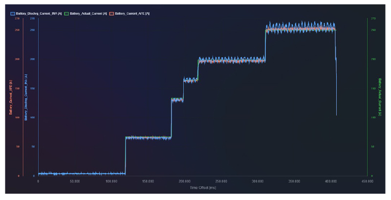
Humanoid locomotion maneuvers such as bipedal jumping, heavy lifting, or rapid stabilization routines demand sudden current surges from the battery pack. To reproduce these conditions, a step-discharge profile was applied, driving the system from zero load to a peak transient amplitude of 250 A. The corresponding 450-second operating window is shown in Fig. 2.
Click image to enlarge
Figure 2: Experimental current sensing performance during a step-discharge sequence
In this high-current setup, the three overlaid curves represent different ways of capturing the same event:
Battery_Actual_Current (green trace): the real current flowing through the battery circuit, measured by laboratory-grade active load equipment and used as the ground-truth reference.
Battery_Dischrg_Current_INA (blue trace): the output of a conventional external instrumentation amplifier mounted as a separate component on the PCB.
Battery_Current_AFE (red trace): the digitized telemetry from the integrated 18-bit current-sensing amplifier inside the L99BM114 analog front end.
The external amplifier trace shows pronounced ringing and signal degradation at high current levels, especially around the 200 A and 250 A steps. In humanoid systems, inverter switching and electromagnetic interference can couple into long PCB traces between the shunt resistor and the sensing IC, degrading the measurement and introducing transient artifacts.
By contrast, the integrated front end tracks the ground-truth waveform closely, with near-zero deviation. This improvement is achieved through two hardware mechanisms:
· Monolithic integration, which minimizes sensitive analog routing on the PCB and reduces susceptibility to motor-generated noise.
· Native high-resolution filtering, which suppresses inverter switching spikes at the source through digital decimation without adding software latency.
This performance comparison shows that while split-chip configurations can suffer from inverter-induced noise under heavy loads, the integrated architecture cleans the telemetry in hardware. By delivering data synchronized to the same clock domain as the voltage channels, the L99BM114 provides the motion-control system with accurate, real-time power metrics. This helps prevent field-oriented control (FOC) loops from saturating and supports stable joint stiffness under extreme stress conditions.
Transient Current Sensing Performance in Charging Conditions
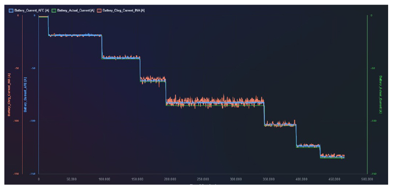
Telemetry accuracy must also be maintained during negative load transitions such as regenerative braking or active energy recovery. To validate signal integrity under these conditions, a step-charging profile was applied from 0 A to approximately -135 A over a 450 s time window, as shown in Fig. 3.
Click image to enlarge
Figure 3: Experimental current sensing performance during a step-charging profile
The dataset includes three synchronized traces:
· Battery_Actual_Current (green trace): the real-world current baseline.
· Battery_Chrg_Current_INA (red trace): the output of the external standalone instrumentation amplifier.
· Battery_Current_AFE (blue trace): the digitized telemetry from the integrated 18-bit current-sensing amplifier in the L99BM114.
The measured waveform shows significant degradation in the split-chip configuration. Between the -70 A and -100 A load levels, the standalone sensor signal is affected by high-frequency ringing and sustained oscillations caused by inverter switching activity.
By contrast, the integrated monolithic front end tracks the reference waveform closely across the full operating range. Because digitization occurs directly on die, the architecture avoids noise-sensitive routing. Digital decimation filtering suppresses inverter switching spikes at the silicon source without introducing phase delay or propagation latency into the telemetry stream.
Consistent filtering performance across both charging and discharging cycles also helps minimize coulomb-counter drift. Reduced capacity-tracking error supports more efficient battery sizing, lowering pack weight and structural inertia while improving overall humanoid agility.
Conclusions
Battery telemetry synchronization has a direct impact on the dynamic stability and reliability of humanoid robots. Split-chip architectures can introduce timing mismatch and capture inverter switching noise. Under transient loads, this may cause the controller to miscalculate cell impedance, leading to current saturation, abrupt reductions in joint stiffness, and balance errors.
The monolithic L99BM114 BMS addresses these issues by integrating voltage monitoring and current sensing on the same die, synchronizing measurements in hardware, and delivering accurate telemetry with minimal delay. For humanoid systems operating under rapidly changing load conditions, that measurement coherence is a key enabler of robust control and dependable operation.