Battery Management Solutions for High-Voltage Energy Storage
Few topics are more important for EVs and HEVs than ensuring robust, reliable battery systems.
Most of the growth in the rechargeable battery industry is expected to be from their increased use in high voltage energy systems for electric vehicles (EV) as well as in marine and home storage applications. These systems will typically employ series-connected battery packs made up of lithium-ion or nickel metal hydride batteries. To maintain the cells in good condition and maximize output power, they require a battery management system (BMS). A BMS also helps extend the life expectancy of battery cells and protect them from damage. Therefore, an important BMS function is to determine the state of charge (SOC) allowing the BMS to govern the capacity remaining in the battery, and also to control the rate of charging or discharging.
In this article, BMS design trends will be highlighted along with the challenges designers commonly encounter in BMS systems. Particular focus will be given to the isolation of communications and transient protection issues where new isolated sigma delta converters with dynamic ranges less than 200mV can be a viable solution. It also covers the benefits of shunt-based current measurement in BMS designs.
Trends in EV Battery Management
The trend in electric vehicles is for the number of cells in stacks to increase beyond 100S (100 cells) and working voltages to approach 1000V. Supporting BMS systems will use several cell voltage monitoring modules networked together that have 2-wire interfaces such as CANbus, Ethernet or SPI. The communications line has galvanic isolation using an Ethernet LAN transformer. This provides an isolation barrier that prevents hazardous voltage from jumping onto low voltage lines. An important note is that the level of isolation (Basic, Supplementary, Double, Reinforced) is not specified by any standard and is left to each customers’ safety engineer to evaluate the environment and determine the safety level required.
Each cell has its voltage checked by the monitoring system with typical tolerances of 0.1% (to the order of millivolts) to determine the state of charge of each cell. This allows those cells that are overcharged to be bled off (passive balancing), which would prevent other cells with lower capacities from being charged. Active balancing redistributes charge between over and undercharged cells.
Integrated protection from short transients that can occur during the installation and wiring of the cells can be handled by Zener or TVS diodes. However, the junctions in these diodes are not designed to manage the amount of energy in a transient created by the sudden disconnection of the battery stack busbar. If this happens, the BMS IC, which is usually connected to the very last cell on the high end of the break, will suddenly go from reading the voltage on a single cell (1S) to the entire stack. In an EV application that can have 100S or more, this energy will puncture through the protection diodes before control loops can react in time to disconnect the entire pack. What is needed in this scenario is a high-speed overcurrent protector to avoid catastrophic damage.
Current Measurement
Shunt-based current measurement is used frequently to monitor battery charge and discharge current. One of the drawbacks of shunt-based measurement is the power wasted due to ohmic heating by the current being measured. In the past, the maximum current that shunt-based measurement systems can work with is 50 amperes. This is now changing with the advent of lower resistance shunts and high dynamic range high resolution sigma delta modulator technology.
Traditionally, Hall Effect sensors measure currents greater than 50 amperes due to the lower power losses incurred. A limitation is that Hall Effect sensors exhibit a wide variation in zero flux output voltage and sensitivity to over temperature threats. Temperature compensation circuit solutions are available but can be expensive.
By lowering the resistance of the shunt, the power dissipated could also be reduced, which allows for higher currents. Shunts have a superior temperature drift characteristic compared to Hall Effect sensors allowing for higher accuracy with digital sigma delta modulation. Therefore, new developments in signal processing will make shunt resistors more attractive for future applications that previously used Hall Effect technology.
Designing the circuit to attach a shunt resistor to a sigma delta modulator is straightforward. A simple filter is needed to remove the effects of harmonics from high frequency switching. The equivalent circuit of a shunt resistor consists of a resistor and an inductor in series. At high frequencies such as harmonics from switching converters or inverters as the inductance changes, the response and the voltage across the element will change accordingly. To ensure that the voltage read across the shunt is due to the current itself and not due to the inductance, an RC network is added in parallel. The values R3 and C1 as shown in Figure 1 are selected according to the following equation:
XL/R3 = R1/C1
Where XL and R1 are the reactance and the dc resistance of the shunt respectively.
High Energy Cell Protection
Battery cell monitoring lines in a stack are vulnerable transient threats in high voltage systems. Consequently, these lines require ultra-fast overcurrent protection to prevent damage to the internal ESD diodes. A good solution is a high voltage (850V) MOSFET device that behaves like a resistor. When the current reaches its threshold (200mA), the device will trip. To reset, the voltage across the device must fall below its reset voltage (typically 15V). A high voltage rating in the disconnection of a battery stack busbar allows the full output voltage of the charger’s bulk capacitor to appear on the A/D input of every cell. This type of protection device also features resettability so once the high voltage transient is removed, the protector returns to its normal state enabling the IC to monitor the battery cell safely again.
For example, Bourns offers TBU High-Speed Protectors (HSPs) with different combinations of voltage ratings and trigger currents. TBU HSPs can react in less than 1µs to transients.
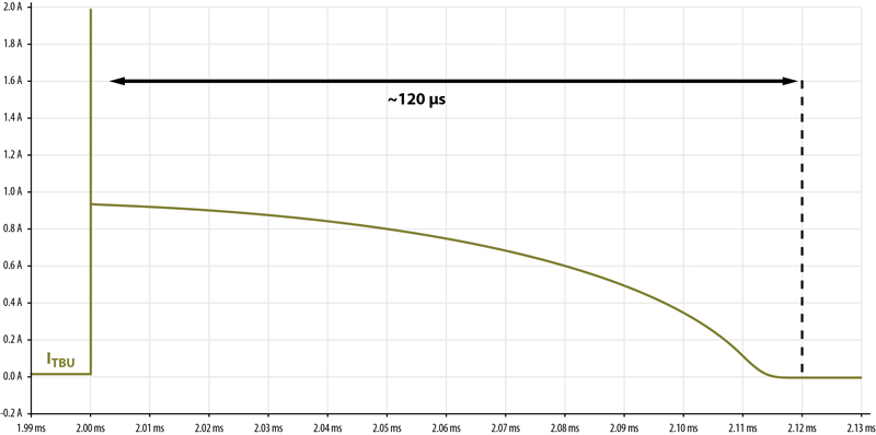
Click image to enlarge
Figure 2. A current surge and the time it takes for the TBU device to go into a protected state (ITBU decreasing to IQ), where the TBU device’s reaction time (current dropping IQ) is about 120 µs.
Benefits of Galvanic Isolation
Isolation barriers serve to protect equipment and humans from harmful voltage surges. Isolation also enables communication between a transmitter and a receiver, referenced to very different ground potentials. In battery management ICs connected together in a point to point configuration, two-wire communications designed to operate over an isolation barrier are used. Providing the isolation needed, signal transformers such as Ethernet LAN magnetics can be ideal. They also offer additional value from an integrated common mode choke that helps reduce common mode noise.
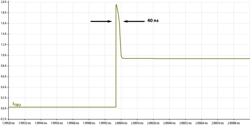
Click image to enlarge
Figure 3. The time it takes for the TBU device to start blocking -- approximately 40 ns.
In battery stack applications with voltage levels higher than 400V, it is common to specify reinforced or double insulation with hi-pot testing of 4KV or higher. Both types of insulation require the use of three layers of insulation. To achieve the required levels of safety while maintaining effective signal integrity and to adhere to budget and form factor size goals, designers many times must make compromises.
LAN transformers twist the primary and secondary wires together to minimize leakage inductance. As the thickness of the insulation used increases, however, it becomes harder to twist the two together and there are added difficulties for winding machines to thread the windings through the toroid. Thus, it can be more practical to use double insulation rather than reinforced insulation because of the narrower wires. The leakage inductance between primary and secondary wires is proportional to the surface area of the insulation between the coils. Therefore, the thicker the insulation of the wire the higher the leakage inductance. LAN transformers are also bulkier -- not just due to wider cores but also due to their creepage and clearance distances. For example, a LAN transformer with a working voltage of 370V in a pollution degree 2 environment must have a creepage distance of at least 7.7mm according to IEC 60950. Consequently, isolated communications with high working voltages using Ethernet magnetics do require a trade-off between safety, size, cost and signal integrity.
In addition, battery monitoring ICs require stable DC bias voltages, which is commonly accomplished using an isolated topology such as “push pull” or “fly back”. By putting an isolation barrier around the power supply, the ground potential difference between the supply ground and the battery IC ground is removed. It also removes the risk of the ground potential appearing on signal lines as a common mode voltage. Power transformers rely on the IEC 61558 standard to determine the required creepage and clearance distances for the relative working voltage and insulation levels.
Leveraging Advanced Technology for BMS Designs
Leveraging the development of BMS solutions that utilize the latest in digital sigma delta modulator technology can be quite beneficial in the development of BMS protection. Using this technology allows component suppliers to deliver a new generation of current measurement traditionally reserved for non-contacting sensors. The advancements made with high dynamic range A/D converters in BMS ICs using high-speed sigma delta modulation enables accurate current measurement above 50 amperes with shunt-based technology. Suppliers such as Bourns have the capability in TS16949 facilities to manufacture shunts with very low resistance by working with thick high purity copper where the maximum current-carrying capability increases with the thickness of the copper.
While several off-the-shelf protection solutions were provided, there are many BMS designs that will require custom solutions for various functions that include direct connection between the shunt and high current busbars. Custom power and signal transformer designs may also be needed for isolated DC-DC supplies and point-to-point communications so that battery management of high voltage EV energy storage systems will have the optimum level of protection for efficient, safe and long-term operation.
Bourns