Author:
Fionn Sheerin, Principal Product Marketing Engineer, Analog Power and Interface Division, Microchip Technology
Date
05/04/2020
 PDF
PDF
Click image to enlarge
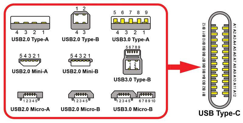
Figure 1: USB Cable Plug Form Factors
The power landscape is getting simpler with industry convergence on USB Power Delivery (PD) standards, and with good implementations USB4 can continue that trend. Ensuring the best possible charging experience across multiple new use cases will depend on several application design decisions.
The main purpose of the USB4 development is to double the data rate compared to USB 3.2 (40 Gbps compared to the prior 20 Gbps) and to enable support for Intel's Thunderbolt protocol. USB4 will exclusively use the USB type-C port, the oval-looking port with the blade down the center famous for accepting cables even when they are inserted upside down. While inserting the cable may be getting simpler, the charging technology behind for USB4 ports must now include USB PD, which adds complexity. Prior generation USB specifications using the type-C port had an option to allow for PD; USB4 requires it.
Power Delivery Required in USB4
The PD specification was revised to include new messages to discover and transition to USB4 mode, but the power schemes are the same. They use a single-wire 300 kHz bus on one of the Configuration Channel (CC) lines of the USB type-C interface for the host and device to discover and negotiate the power and data they will be transferring (Fig. 1). The other CC line assumes the role of "VCONN," a dedicated power source for the electronic marker (an identification circuit inside the USB cable). The power delivered between USB ports is transferred on a separate set of wires within the connector (labeled "VBUS;" see Fig 2). When two PD devices connect, they use the CC wire to detect each other, communicate power capabilities (which voltages, and how much power at each voltage), understand which device should source or sink power, negotiate how much power to deliver, and then provide that power on VBUS. This 300kHz digital signal is also used to identify that the USB connection can support a USB4 link, so there is no way to implement USB4 without this communication. USB4 ports are not required to supply or receive any power beyond a minimum 5V / 900mA; but they must support PD communication to function as USB4.
Historical Power on the Universal Serial Bus
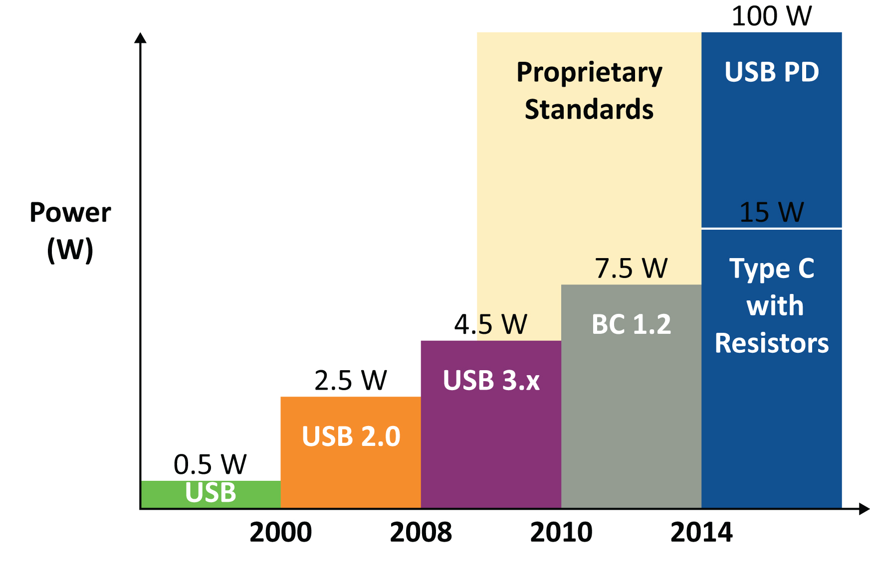
To look at the charging user experiences in USB4, it is helpful to understand the history of power across the USB connector (see Fig.2). The Universal Serial Bus was originally meant for serial data communication, with a maximum of 100mA of current in the cable. USB 2.0 specifications were limited to 500 mA in the VBUS line; this was suitable for powering basic computer peripherals. USB 3.0 standards increased the current limit to a 900 mA, but with portable devices converging on a single connector for data and power, it was not enough. The USB committees released the battery charging (BC) specifications, ending with the BC1.2 specification in 2010, allowing 1.5A (7.5W); and at that point, many smartphone manufacturers gave up on being USB specification compliant.
This led to a proprietary charging protocol free-for-all, using voltage levels set on the D+ and D- lines (USB data lines): 2V on one line and 2.7V on the other might give a 10W charge; 2.7V on both data lines might signal a 12W charge; 3.3V on each line would trigger a charger to provide 20V (which could be damaging, if applied by mistake). These methods were not interoperable, and results were unpredictable. In addition, the data lines used to decide charging levels were no longer available for data. A port can transfer files, or it can charge faster, but not both. Anyone who has ever experienced a phone dying while charging - that port was possibly a data connection supplying 500 mA under the USB 2.0 specifications.
Click image to enlarge
Figure 2: USB Power Policies over Time. The proprietary standards varied by manufacturer, while new USB specifications generally maintained backwards compatibility with prior specifications.
This issue motivated the first PD specification (revision 1), creating a universal standard for charging at alternate voltages (more than 5V) using traditional 4-pin USB cables. Maintaining backwards compatibility required adding a handshake signal to the VBUS line itself, which was complicated to implement and the whole thing was scrapped without significant adoption. The USB-IF would prefer everyone forget this spec was ever written and practically speaking, everyone should. This approach is no longer valid or supported.
Today, there are PD versions 2.0 and 3.0, and the included programmable power supply (PPS) specifications. These were created alongside the USB type-C port, with added signal connections. The differences between version 2 and 3 are mostly in the CC communication details. Both are backwards compatible with prior USB implementations (excluding PD revision 1) and the user experiences will be the same. Devices negotiate charging profiles, potentially down to 20mV increments (under PPS implementations). PD capable devices can (but are not required to) support up to 100W of power transfer within the specification (5A at 20V). The proprietary schemes to advertise alternate charging profiles using the data lines are explicitly forbidden, but USB type-C also allows for simplified 1.5A and 3A charging at 5V (recognized by resistors on the CC pin, instead of the digital signal). Type-C ports do not require PD, but PD does require a type-C port, which is where USB4 changes things (see Fig. 3); USB4 uses PD communication to enable the USB4 mode.
Click image to enlarge
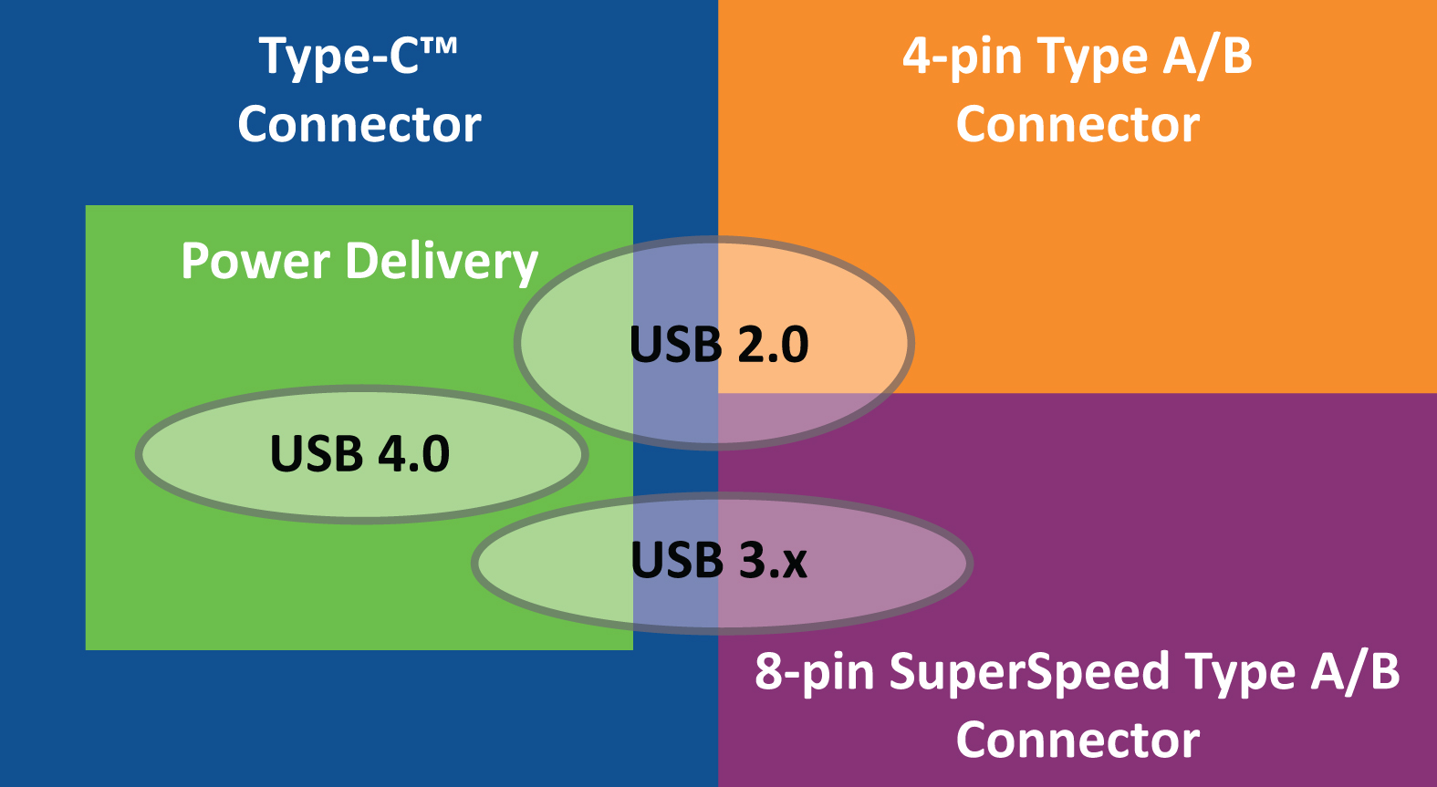
Figure 3: USB Data and USB Power Relationships - USB 2.0 can exist on any USB cable, with or without power delivery on a type-C cable. USB3.x requires a cable with additional superspeed lanes, with or without power delivery on a type-C cable. USB4 can only exist on a type-C connection, with Power Delivery communication. Power Delivery can only exist on a type-C connection but does not require data.
While new devices will follow the new streamlined specifications, the complexity in USB charging comes from all of these legacy standards, all of which still exist on older ports, and a new USB4 port may be connected to any of those legacy ports (see Table 1).
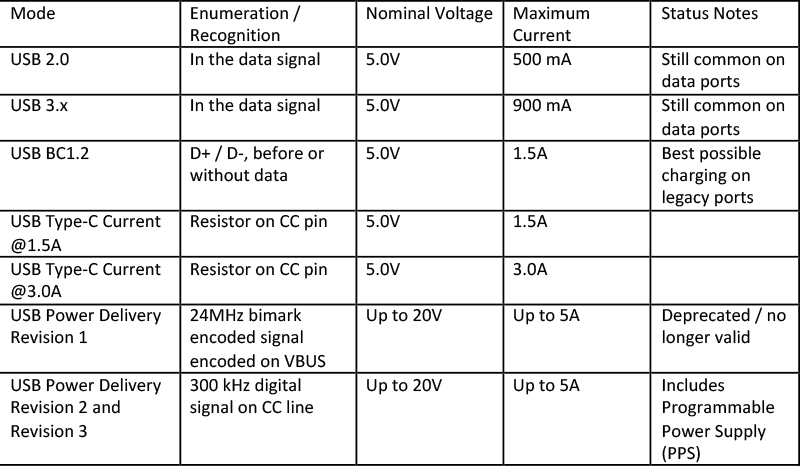
Click image to enlarge
Table 1: USB Power Connections
Use Cases and User Experiences
Trying to maintain five generations of backwards compatibility creates a complicated landscape of possible power connections. It leaves a big question about what happens to all the older USB ports and cables, and users may still be wondering "will it charge?" Fortunately, ignoring the proprietary specifications, most of that history falls into just a few possible user experiences. While they will all charge, they may not all charge quickly.
There are fundamentally four use cases to consider in the context of USB4:
1. A legacy charging port connects to a USB4 type-C device using an adapter cable
2. A USB4 type C charger connects to a legacy port using an adapter cable
3. A USB4 type C port connects to a non-USB4 type C port with a C-C cable, and places a resistive divider on the CC line
4. Two type-C ports connect with a C-to-C cable, and communicate on the CC lines; either or both could be USB4 devices
In terms of USB standards, the 8-pin Apple Lightning connector carries the same signals as a legacy USB 3.x cable. USB4 ports connecting by type-C to Lightning adapter cables will behave similarly to type-C to micro-B, or type- C to type-A cables, in terms ofpower functionality. The following is a summary of what to expect with each charging use case:
Legacy Charging Port Connected to a USB4 Device Using an Adapter Cable
Legacy ports like the type-A and type-B ports may have been created before the Type-C specifications (see figure 1). There wasn't, and will not be, a requirement for these ports to implement any specific faster charging scheme. A USB 2.0 port could default to 500 mA charging, or a USB 3.x port could default to 900 mA. The good news is that most newer USB ports do support BC1.2 and will provide 7.5W. It doesn't matter what kind of adapter cable is used, the USB4 or type-C device connected into the legacy charge port cannot draw more than 7.5W of power without violating the USB specifications.
USB4 Charging Port Connected to a Legacy Device Using an Adapter Cable
In cases where a USB4 charging port is connected to a legacy device, a few possible outcomes could happen. The USB4 port could advertise 1.5A using BC1.2 standards, and the cable could carry 7.5W. If the USB4 isn't set up to support the extra overhead of BC1.2, the USB4 port will need to default to 500mA for a USB 2.0 data connection, or 900 mA for a USB 3.x data connection. This will lead to some user frustration, as the fanciest USB port may result in the slowest charging when used with adapter cables.
USB4 to Non-USB4 Type C, with Resistive Dividers
If either the power provider or consumer is using the type-C resistive divider method to advertise power capabilities, that will dictate the power transfer. The USB4 device will not be able to communicate on the CC lines, but it will still recognize the attachment, the provider/consumer relationship and the current limit (1.5A or 3A) using current sources or resistors connected to the CC lines. The bus voltage will stay at 5V, and the load device will be able to draw power up to 7.5W or 15W. Since the device knows it isn't in PD mode, it may indicate that it is not fast charging for a clear user experience.
Type-C to Type-C, with PD Communication
This is potentially the most capable USB4 connection in terms of power transfer, but the exact results will vary. The two connected devices will negotiate a power contract based on their capabilities, up to 20V and 5A. Part of the negotiation is the role as a provider or consumer of power. It is possible to connect two power consumers, who would negotiate not to transfer power (and this is a valid use case for data transfer between portable devices). Provider ports may be marked with a battery symbol, so in many cases users will know which ports on a dock or a laptop are setup to provide power. In that case, the port providing power must be able to supply at least 1.5A at 5V (7.5W, same as BC1.2) to use a USB-IF approved charging logo. Higher power levels are not guaranteed to be available even in a type-C port labeled with a charging icon. Since the power contract could be any power level from 7.5W to 100W, the user will only know what is happening if one of the devices reports information about the contract (indicating a power level or fast charging connection). This use case certainly has the potential to create unpredictable and frustrating user experiences, but with good reporting and good user interfaces, this could also be a perfect user experience.
Conclusion
The addition of USB4 will add a lot of bandwidth and capabilities to the USB applications that can use them, but USB 2.0 and USB3.x will continue to live in applications that can live with less data transfer. The power use cases will multiply, but with smart application design this does not need to create bad user experiences.