Better LED Intensity Control in Video Displays
Emulating 16-bit resolution
When a video display application uses a pulse-width modulated LED driver such as the MAX6975, higher PWM resolution is needed to provide gamma (visual effect) correction, LED characteristic matching, and ambient light adjustment to the 8-bit or 10-bit video information. This article will explain how to emulate 16-bit PWM resolution for the video application even though the MAX6975 only has a native PWM resolution of 14 bits. For better power efficiency and color consistency, the intensity of an LED is typically controlled by regulating the duty cycle of a pulse-width modulation (PWM) period through an LED driver. A PWM period usually consists of a number of clock cycles equal to the 2 to the power of the number of control bits (2CONTROL BITS). The control-bit resolution for consumer electronics applications is normally 8 bits. Thus with 8-bit PWM resolution, 256 different intensity levels can be provided and the corresponding PWM period consists of 256 clock cycles. For a typical consumer-electronics clock frequency of 32kHz, a PWM period lasts about 256/32kHz, or 8ms. Consequently, the PWM refresh rate is about 125Hz. Together, this PWM resolution and refresh rate provide enough lighting intensity adjustment, and avoid the flickering effects that can be seen by the human eye. However, for the latest generation HD displays, that resolution is not sufficient and thus the driver resolution must be extended to provide finer granularity.
It is a challenge to meet the requirements for both the 16-bit PWM resolution and the 2kHz refresh rate of the latest displays. The 16-bit resolution leads to a PWM period with 216 = 65,536 clock cycles. The corresponding clock frequency for a 2kHz PWM refresh rate is 2000 x 65,536 = 131.072MHz. Sending data over a CMOS interface at this speed becomes unreliable, even for reasonable distances. The real issue is that the LED driver's output ports cannot be switched on/off fast enough with the loading of the LED and associated wiring. Without accurate turn-on/off timing, the benefit of 16-bit resolution cannot be realized. As a compromise, a group of PWM periods of less than 16 bits can be used to emulate a full 16-bit PWM period. By using this approach, the desired 2kHz PWM rate can be maintained at a lower clock frequency since the number of clock cycles is reduced in each PWM period. The visual effects of 16-bit resolution can be maintained, since the human eye cannot distinguish change/flicker once the PWM refresh rate is faster than a few hundred hertz. Consider the example of a video camera operating at, or near, 1/2000 shutter speed. The camera will capture frames at lower resolution, but this is much better than capturing a black screen for lower refresh rates. Although the shutter speed can be very high, a video camera still captures 60 frames at every second. The averaging effect of these multiple video frames can still resemble a picture close to the desired 16-bit resolution. The 16-bit resolution can be divided into different MSB/LSB (most/least significant bit) ratios for the emulation. There will be a number of PWM periods with the resolution of the MSBs: 2 to the power of the number of the most significant bits (2MSB). The number of periods equals the resolution of the LSBs: 2 to the power of the number of the LSBs (2LSB). There can also be different methods of bit distribution among the PWM emulation groups. A simple approach is to let the LSBs decide if the last clock cycle of each group should be on/off; the MSBs decide the remaining clock cycles. Restated simply, the clock cycles' on-/off-times determined by the MSBs are all the same for all groups.
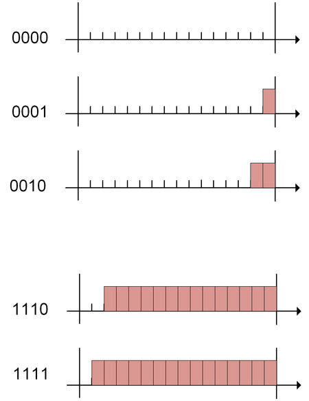
Let's use a 2/2 split emulation of a 4-bit resolution as an example to detail the approach. Figure 1 shows the direct 4-bit implementation of 16-position PWM waveform patterns.
A 2/2-split emulation will create four 4-position PWM groups. The 2 LSBs are used to select at which group the last clock cycle should be on. The 2 MSBs are used to determine the on-/off-pattern of the remaining three clock cycles. Figure 2 shows the effect of the 2 LSBs on the emulation PWM waveforms when the 2 MSBs are 0s.
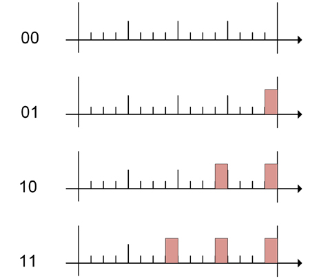
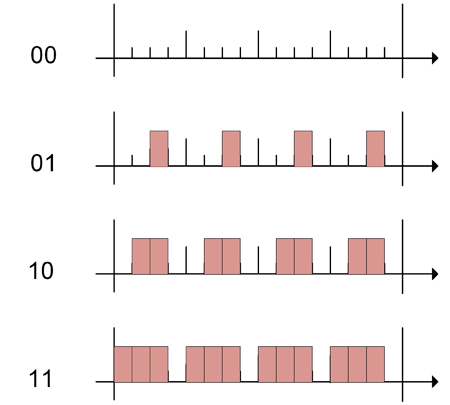
Figure 3 shows the effect of the 2 MSBs on the emulation PWM waveforms when the 2 LSBs are 0s.
This approach can be used with the MAX6975 LED driver's built-in LVDS interface to emulate 16-bit resolution. It is done with a split of 14/2. A 16-bit video frame will be displayed by four 14-bit video frames of light, by one clock cycle, on/off differences. A simple encoder generates these 14-bit PWM codes using the 16-bit PWM code as input. The encoder uses the 14 MSBs as the base for the 14-bit code, and adds another bit depending on the pattern of these two LSBs. Figure 4 shows the emulation encoder. The first 14-bit PWM code takes the MSBs as they are. The second code adds the MSB of these two LSBs. The third code adds the OR operation of these prior two, and the fourth code adds the AND operation.

There are two small drawbacks for the proposed emulation approach. First, there will be some missing PWM codes at the highest brightness region. As shown in Figure 2, some emulation PWM codes will be fully turned on when selections of the MSBs and LSBs are combined. The full turn-on could not be produced with the MAX6975's original designed operation. The effect of these missing codes, however, will not be noticeable. These codes are near full brightness and not used often. Even when these codes are used, human vision is not sensitive to the slight variation of light intensity when it is that bright. Second, the information sent to MAX6975 will be four times more or faster if the 60 video frames-per-second display rate is to be maintained. The data interface of the MAX6975 is still fast enough to supply many chips in a serial chain, but the number of chips in the chain will be reduced proportionally. At a clock frequency of 32MHz, 32,000,000/(14 x 24 x 60) = 1,587 x MAX6975 chips can be put in a serial chain to share the same data interface at a frame rate of 60 video frames per second. This number will be reduced to 396, if four emulation frames need to be delivered for each video frame. A video array of 32 x 32, or up to 56 x 56, pixels, can still be driven by a single data interface with all chips in a serial chain. There is, finally, a small difference compared to the general emulation approach that is also worth noting. Each PWM frame is normally repeated 32 times as subframes for the global intensity control of the MAX6975. Therefore, the MAX6975's 14/2 implementation of a 16-bit resolution will also have each of these four emulation PWM frames repeated 32 times. www.maxim-ic.com
 Single.jpeg)