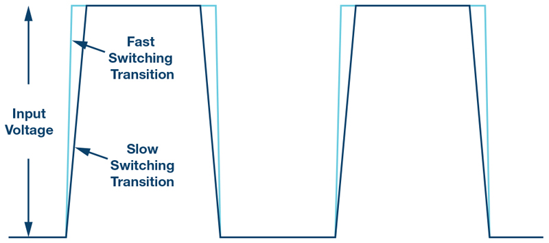
Figure 1. Switching transitions in a switch-mode power supply with input voltage at the switching node
Fast switching transients in switching regulators are advantageous because they drastically lower the switching losses in a switch-mode power supply. Especially a thigh switching frequencies,the efficiency of a switching regulator can be greatly improved. However, fast switching transitions also yield some disadvantages. Interference in the frequency range of the switching transitions between approximately20MHz and 200MHz increases dramatically. This makes it important for the switch-mode power supply developer to find a good compromise between high efficiency and low interference in the high frequency range. In addition, the innovation of Silent Switcher® technology from Analog Devices has created new possibilities for generating minimal radiated emissions even with very fast switchingedges.
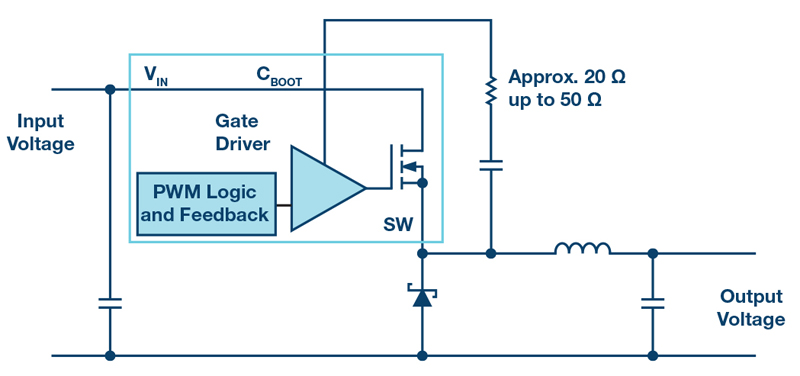
Figure 1 shows both a fast and a slow switching transition.A fast switching transition results in a stronger coupling of interference to neighboring circuit segments.PCB traces that rapidly change voltages cancapacitively couple with adjacent lines that have high impedances. PCB traces that rapidly change currents can inductively couple to adjacent traces. By slowing down the switching transitions, it is possible to minimize these effects. Figure 2 shows a proven technique for nonsynchronous switching regulators. Here, one of the two switches is implemented with a Schottky diode.A resistor in series with the bootstrap capacitor CBOOT,which supplies the gate voltage of the high-side n-channel MOSFET, leads to slower switching of the switch. This trick is used in integrated switching regulators when there is nodirect access to the gate path of the power MOSFET. If a switching controller is used with an external MOSFET, a resistor can also be inserted into the line of the gate path. Resistance values of less than 100 Ω are common.
Click image to enlarge
Figure 2. Slowing down of switching transitions in a nonsynchronous buck converter with a bootstrap resistor
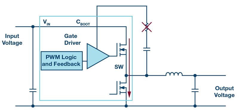
However, most modern switching regulators are synchronous switching regulators with high-side and low-side active switches. Here, the switching transitions cannot be easily slowed down with a resistor in the CBOOT path. If a resistor in series with CBOOT were also to be used here as shown in Figure 3, the switching of the high-side switch would also be slowed down. However, this could lead to the low-side switch not being completely turned off.Thus,it could be possible for both the high-side and the low-side switch to be temporarily on at the same time.This would lead to a destructive short circuit from the input voltage to the ground. This is especially critical because the speed of the switching transitions is also affected by parameters such as operating temperature and a certain variability in semiconductor manufacturing. Thus, even with testing in the lab, no guarantee of safe operation can be given. For slowing down switching transitions in synchronous switching regulators with integrated switches, a synchronous switching regulator in which the speed of the switching transitions can be set directly, with internal circuitry, should be used. An example of this is the ADP5014from Analog Devices. In these integrated circuits, it is internally ensured that while slowing down switching transitions, both switches are not conducting at the same time and hence no short circuit can occur—and all this without a resistor in the CBOOTpath.
Click image to enlarge
Figure 3. A synchronous buck converter with a possible short circuit due to the slowing down of the high-side switch transition
Regarding the topic of fast switching transitions, a very important innovation from recent years should not be neglected. Silent Switcher technology from Analog Devices enables the radiate demissions from the fast switching edges to be reduced significantly, by up to 40 dB (a factor of 10,000). As a result, switched-mode power supplies with extremely fast edges and with only minimal EMC problems can be developed. Silent Switcher device avoids the need to reduce the switching transition speed for the purpose of reducing EMI in most cases. The huge trade-off between maximum conversion efficiency and minimum generated interference has largely been eliminated through the Silent Switcher technology.