Author:
Jose Quinones, Senior Applications Engineer, Programmable Power Management, Qorvo
Date
05/30/2022
 PDF
PDF
Click image to enlarge
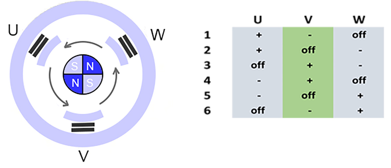
Figure 1: Windings of a three-phase brushless DC motor are driven in a set sequence
The first idea that electricity could be used to produce rotary motion originates in the 1740s in experiments by a Scottish Benedictine monk, Andrew Gordon. It took nearly another century before a practical battery-operated version appeared in 1834 and then, through the work of Tesla and others, the ground was laid for the motors we see today in every walk of life.
One of the obvious uses of motors was to replace manual labor with ‘powered’ hand tools, so portable drills, circular saws and other products were designed, but mains AC powered, with inconvenient power cords, restricting how portable they could be. DC motor design was advanced, but battery technology was not, so ‘cordless’ products were initially not practical, at least ones that were light enough to carry and with useful power.
Lithium-ion batteries are a game changer for portable tools
With improving energy density from Nickel-Cadmium and then Lithium-Ion chemistries, power available and run-time from batteries became acceptable, and the first power tools appeared using the simplest and cheapest ‘brushed’ motors. Mechanical brushes in motors provide ‘commutation’ – the action where windings on the rotating armature are energised in sequence depending on the rotor position, so that the resulting magnetic field always acts against the stator magnets to produce rotational torque. However, these motors are subject to wear, they generate continuous arcing and efficiency is at best around 80%, limiting power available and generating uncomfortable heat under load. Speed and torque control are relatively easy, at least at higher speeds, but the products had to wait for the introduction of electronic ‘switched mode’ techniques to vary the voltage and provide motor control without excessive dissipation.
We have high expectations of modern power tools
Modern power tools are expected to be compact and light weight, powerful, speed controllable, have small but long-lasting batteries and not least, they need to be affordable and maintenance-free. ‘Brushless’ DC (BLDC) motors are the current best solution, with an electronic technique to achieve commutation. Typically, three windings are powered in sequence as part of the stator, with the magnets on the rotor.
Leveraging improved magnet technology, BLDC motors have an efficiency that can be around 96% and performance is also improved over brushed types with a flatter torque curve at all rated speeds. However, there is a down-side, for maximum performance, a complex drive to the three stator windings is necessary with an applied voltage in an exact timing sequence, which depends on the precise current rotor position and the demanded speed. To maintain rotation, the windings must be driven in six stages in combinations of no drive, positive current and negative current (Figure 1).
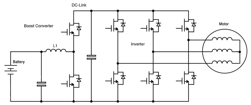
The drive is most conveniently generated by a three-phase bridge arrangement of six semiconductor switches, typically MOSFETs, providing the six drive combinations, with some ‘dead’ time between each phase where no switch is on (Figure 2). Each phase in the sequence is initiated in turn, triggered by a shaft sensor, as the rotor moves progressively around 360 degrees. With no further control, the motor will spin up to a maximum speed set by the supply voltage to the bridge, any delays in sensing and reacting to rotor position, and the inductance of the windings. As speed increases and the time duration of each drive phase decreases, Inductance limits the peak current and hence torque to progressively lower values.
Click image to enlarge
Figure 2: A bridge circuit generates the three-phase drive for a BLDC motor. Shown with a buck converter to regulate the battery voltage for the DC-Link
Pulse width modulation enables speed control
To control the speed to a demanded value, the drive voltage to the windings during each phase can be pulse width modulated (PWM) so that the winding sees a variable average value, equivalent to varying the supply voltage to the bridge. The rotor sensor is already supplying shaft rotation rate information so a feedback loop can be implemented with the PWM drive, to enable accurate speed control. The PWM signal itself has a repetition rate which is often tens of kHz with MOSFET switches and typically more than double the maximum rate at which the three-phase bridge switches states, or equivalently, rotor speed.
The PWM pulses to the power switches and their complex timing is best generated by a microcontroller, along with appropriate pre-drivers to scale output voltage to a suitable value for the switch gates and to provide the high peak current required. An additional complication is that in a bridge, the gates of the ‘high-side’ switches are offset from ground, so there has to be a ‘floating’ supply voltage for the driver, higher than the battery voltage. Also, the PWM drive signal from the microcontroller has to be ‘level-translated’ up to the high-side MOSFET gate drive voltage. The rotor positional information has to be scaled and ‘digitized’ as an input to the microcontroller along with winding current indication for control and overload protection. Signals representing temperature and an analog speed demand, typically from a potentiometer on the tool trigger, also require analog to digital conversion. The microcontroller itself requires several power rails and these need to be derived from the DC input, which might be from a range of battery voltages.
All control electronics must typically fit in a tool handle
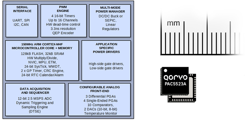
The electronics to achieve all this is complex and must be fitted in the minimal available space in the tool, often within the handle, representing a significant engineering challenge. However, the market for hand tools is so huge that dedicated controllers have been designed by companies such as Qorvo integrating all the functions into a tiny IC, as part of their range of Power Application Controllers (PACTM). A typical product in the series will have a range of serial interfaces, a PWM engine, a configurable power manager, application-specific power drivers for external MOSFETs, multiple sophisticated ADC channels, up to 14, and configurable analog inputs. At the heart of the range of devices is an ARM Cortex M0 or M4F controller running at 50MHz and 150MHz respectively (Figure 3).
Click image to enlarge
Figure 3: A Qorvo high-performance BLDC motor controller and driver, suitable for power tools
One of the many advantages of the Qorvo PAC devices is the ability to interface to different rotor position sense and control methods. Accurate positional sensing is vital to achieve the optimum performance from a BLDC motor, but the common method using typically three hall effect sensors is expensive, requiring extra electronics and precision mechanical fitting. Another possibility is a rotary encoder but ‘sensorless’ techniques to ensure correct commutation can be very cost-effective. A popular method is to monitor back EMF from the winding that is un-energized at any point in time and initiate the next commutation phase when the back EMF crosses zero. The technique does however require a separate ‘open-loop’ drive to the motor windings on startup, when there is no back EMF. Processing sensor signals and combining them with speed or torque demand can be optimized for best performance with use of advanced techniques such as Vector or Field Oriented Control (FOC) which monitors winding currents along with positional information. FOC can be ‘sensorless’ by estimating position and speed based on current and winding voltage. The result is high torque, low consumption, smoother operation and low noise. The controlling algorithms for FOC are complex, but are provided by Qorvo as part of the PAC complete motor control solution. Algorithm ‘auto tuning’ for a specific motor type is provisioned, along with a variety of fault detection features.
For power tools, the switches in the bridge circuit must be rated for high peak power and therefore discrete power MOSFETs are typically used, with appropriate heatsinking. For low power applications to about 20W, PACTM devices are available with the power switches integrated, for the smallest possible form factor.
The future is better tools but smaller space for the drive circuit
For the future, motor, magnet and battery technology will incrementally improve for smaller, lighter and more powerful tools, placing more emphasis on efficient and miniaturized electronic drives. Also, battery voltages are likely to rise to keep current within bounds as power increases. Anticipating this, Qorvo’s power application controllers have already enabled the effective integration of all control, drive and power management features into chips of a few square millimeters in size with parts are available rated all the way up to 600V. Newer semiconductor technologies using wide band-gap materials, particularly Qorvo’s silicon carbide FETs (SiC FETs), promise lower losses, also shrinking the size needed for the power switches.