Breaking the Mold – SiC FETs as Circuit Breakers

Mechanical circuit breakers have been successful because of their low loss and relatively low cost compared with alternatives. Now, wide band-gap semiconductors are making solid state circuit breakers more attractive
Figure 1: A JFET (left), SiC FET cascode (middle) and a dual gate SiC FET cascode (right)
Mechanical circuit breakers provide a secure means to make an almost lossless connection when on, and provide complete isolation when off, but they have their drawbacks. They are relatively slow to make and break and they arc across their contacts, particularly with DC, resulting in a limited operating life. New applications for mechanical circuit breakers, particularly in EVs, are now pushing parts to their limits, with running currents measured in hundreds of amps and prospective fault current in thousands. When it takes perhaps 10 milliseconds to make the disconnection, that’s tens of Joules of let-through energy after a short circuit, which could do significant damage.
Solid state breakers have been an option with limitations
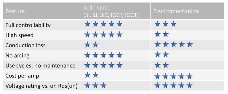
Solid state circuit breakers (SSCBs) have always been an option for much faster disconnection times, complete absence of arcing and long service life, but have had limited voltage rating, higher cost and higher conduction losses than their mechanical counterparts. When a SSCB is implemented with IGBTs, the unavoidable saturation voltage causes excessive power loss above a few tens of amps, forcing adoption of substantial heatsinking, adding to an already-costly solution. Silicon MOSFETs with their low, controlled on-resistance, drop much lower voltage than IGBTs at low current, but as current rises, so does power, but with the square of current. This means that at say 500 amps, an IGBT might drop 1.7V dissipating 850W, while a MOSFET would need an on-resistance of 3.4 milliohms for the same power. While this is in the realms of modern MOSFET technology at low voltages, these on-resistance levels are not currently available in single devices at ratings needed for typical EV battery voltages higher than 400V. Ten in parallel might get close but costs spiral and double again if bi-directional current flow is required, as is normal in EV applications. The cost of a solid-state solution is therefore a major hurdle, even if the lifetime maintenance cost of an electromechanical solution is factored-in. Table 1 gives a summary of the pros and cons, solid state v. electromechanical.
Click image to enlarge
Table 1: Solid state and mechanical circuit breaker comparisons
Silicon carbide is becoming a viable technology for SSCBs
Wide band-gap semiconductor switches are now available with inherently better specific on-resistance with die area (Rds.A) than silicon superjunction MOSFETs, so they can be considered for SSCB applications. The advantages can be seen at the fundamental level when the trade-off Rds.A (drain source resistance times die area) versus breakdown voltage is considered: SiC is theoretically around 10x better than silicon, so for the same rated voltage and on-resistance, die can be 10x smaller, or conversely, for the same die area as silicon, on-resistance can be 10x smaller. As a bonus, SiC will operate at a peak temperature more than double that of silicon and anyway has a far better thermal conductivity as a material, making handling of peak power dissipation much more secure.
A SiC switch can be fabricated as a MOSFET or a JFET (Figure 1, left), with the latter showing a better Rds.A figure of merit. In power conversion switching technologies, the normally-on characteristic of the JFET with zero gate voltage is seen as a disadvantage, although some applications can benefit from the fact that the device fails short in the absence of gate control. The SiC JFET can however also be connected in a ‘cascode’ configuration with a low voltage silicon MOSFET where the combination becomes normally-off and more easily controllable with a simple 0-12V gate drive. This is termed a SiC FET. (Figure 1, middle). A cascode has the small penalty of about 5-15% higher on-resistance than a single SiC JFET because of the series low-voltage MOSFET included, but a version of the cascode where both device gates are brought out for external control allows on-resistance to be an absolute minimum by fine tuning the drive voltages. This device is called a ‘Dual Gate FET’ or DG FET (Figure 1, right). In the SiC FET and DG FET construction, the co-packaged low voltage silicon MOSFET die is ‘stacked’ on top of the SiC JFET die as shown.
A SiC JFET can sense its own temperature
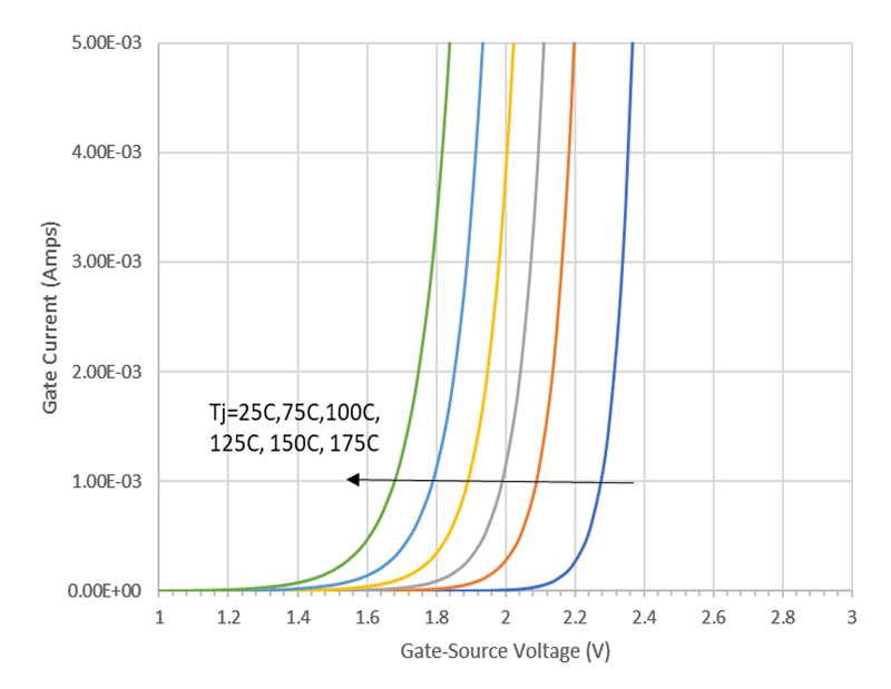
The SiC JFET has a gate which looks like a forward biased diode with an applied voltage of around +2V. Under this condition, the JFET is hard-on and for a fixed bias current of say 1mA, there is an accurate relationship between die temperature and the resulting gate voltage (Figure 2). With the gate connection available with a DG FET, this effect can be used to provide an exact and fast die temperature measurement for protection and long-term state-of-health monitoring for the device. In SSCB applications with a continuous high current this is a valuable function.
Click image to enlarge
Figure 2: The ‘knee’ voltage of a SiC JFET gate has an accurate relationship to die temperature
A practical solution
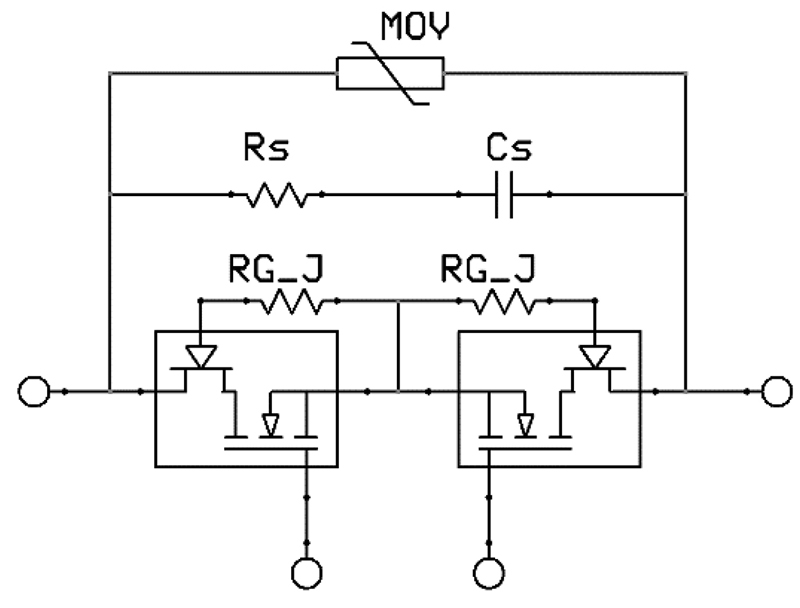
A bi-directional SSCB can be as simple as Figure 3 using SiC FET cascodes. The gate resistors on the JFETs control switching speed to practical levels to avoid instability and EMI and the ‘snubber’ network Rs, Cs helps damp any voltage overshoot on switch-off. SSCBs inevitably have significant external connection inductance and associated stored energy and the SiC FET has a robust avalanche rating to withstand resulting voltage spikes on turn-off, but the MOV shown helps to clamp the voltage as well and is more cost-effective than using higher voltage rated SiC FETs which would anyway have higher Rds(on).
Click image to enlarge
Figure 3: Using SiC FETS as a bi-directional solid-state circuit breaker
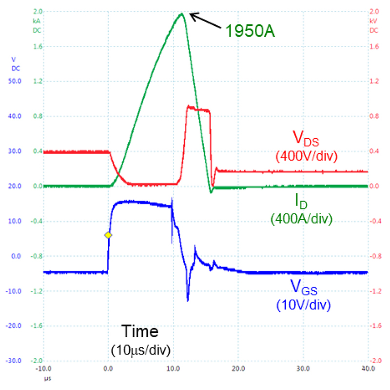
In practice, our goal of a SiC FET SSCB to improve on an IGBT, with an overall on-resistance of around 3 milliohms, would be configured from paralleled SiC FET die. For a unidirectional switch, this could be, for example, six paralleled9mohm, 1200V devices from UnitedSiC giving a combined rating, including package parasitics, of 2.2 milliohms rated at 1200V and greater than 300A, that can be achieved in a small SOT227 standard footprint, comparable with a similarly rated IGBT solution. Figure 4 shows this arrangement interrupting a peak fault current of 1950A with no drama.
Click image to enlarge
Figure 4: A SiC FET SSCB interrupting nearly 2000A safely
The positive temperature coefficient of the SiC FET on-resistance helps to ensure that device share current well, contrasting with IGBTs which do not have a natural balancing effect at low currents
The future for SSCBs
Mechanical circuit breakers may currently have the edge on price, but they are still not a low-cost item, especially in automotive grade. As the market for circuit breakers expands on the back of ballooning EV sales, the solid-state option will benefit from economy of scale from the use of SiC in inverters and reduce in unit cost. This is along with the on-going price reduction that anyway is occurring with wide band-gap semiconductor technology which is still in its infancy and some distance from its theoretical performance limits and best process yield. It is predicted, for example, that the Figure of merit Rds.A for SiC FETs will improve further by 2x – 3x in the coming years with wafer costs halving.
With the benefits of fast switching and no arcing along with the real cost savings of being maintenance-free, SSCBs using SiC FETS will surely become the preferred solution. Even the comparison of losses will be less of an issue when SiC FET Rds(on) becomes comparable with mechanical contact resistance and certainly much lower than that of external cable connections.


