Brushless DC Motors and Their Drives - Design Considerations and Challenges
Applications for motors are vast and choosing the right type and its associated drive is not simple
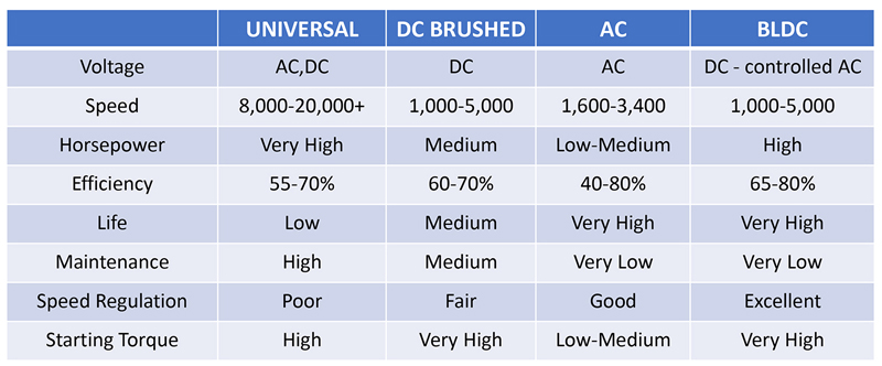
Figure 1: Comparison of motor performance for the same frame size (source: Groschopp)
From their simple beginnings in the 18th century, motors have become ubiquitous, consuming more than half of current global energy production, according to ‘4E Electric Motor Systems Annex’ (EMSA). It’s also stated by the International Energy Agency (IEA) that typically 95% of a motor’s lifecycle cost is the electricity that powers it, so anything that improves efficiency in the operation of a motor is welcome. This can be achieved with ‘smart’ control, which not only makes the motor more flexible and efficient in its job, but also lowers operating costs and energy draw, reducing environmental burden or extending battery life. Legislation is also forcing the issue, with IEC 60034-30-1 for example, setting efficiency levels to be achieved for line-operated AC motors.
Motor types in common use
There is a wide range of motor types in use, depending on the application. In a typical affluent western home for example, Qorvo estimates that there might be 14 brushed DC motors, 26 brushless DC, 48 AC induction and 4 universal AC-DC motors. In total 31 battery-powered and 61 line-powered.
AC induction motors dominate both domestically and in industry because of their relative simplicity and reliability. In basic form they are low cost and have no brushes to wear and their speed has some ‘slip’, that is, they are almost synchronous with the AC drive frequency or a multiple. Single-phase types require special starting methods and are not very efficient but are versatile, whereas three-phase versions self-start with better running efficiency making AC induction motors ideal for constant load/speed applications such as pumps and fans. When variable speed is required, a Variable Frequency Drive (VFD) can be utilized, but when added to a ‘standard’ motor, problems can arise with stress to insulation, EMI and common-mode currents through the motor frame.
For a DC or universal AC/DC supply, a motor has brushes which force commutation and rotation by sequentially energizing coils as the motor spins. These motors can be low cost and provide good performance with high starting torque, making them popular for small tools and appliances. The brushes do wear however and there is often a high level of electrical and audible noise. Speed control with optional closed loop regulation is achieved, often with poor efficiency, by varying the DC or AC supply voltage or typically with phase angle control of AC, with field coil tap-switching a possibility.
The motor type that is coming to the fore is the Brushless DC type (BLDC), basically a reversed-brushed DC motor, allowing the brushes to be removed. These offer better performance, improved efficiency and long life. The downside is that a multiphase AC supply must be provided from a VFD but this does give speed and torque control and the potential to tailor these parameters to the load requirements for energy and process efficiency savings, which can quickly cover the initial cost of the VFD. For this reason, BLDC motors are favored in hand tools with a battery supply and in appliances with their AC input rectified and power factor-corrected as a supply to the VFD.
Some of the headline characteristics of motor types mentioned are shown in Figure 1, all for the same physical size.
BLDC motors
Looking now more closely at BLDC motor and their drives, Figure 2 shows the sequence of coil energization needed for a three-phase type. Voltages are applied with some ‘dead’ time, from a bridge arrangement of switches (Figure 3) which could be IGBTs or MOSFETs, but increasingly wide band-gap devices such as SiC FETs as shown. The sequence of switching is triggered by a shaft sensor or other method as the motor spins and feedback of rotor angle, speed and current allows control of torque and torque ripple, which can cause unwanted vibration. Without feedback, the motor would spin up to a maximum speed limited by system delays and coil inductance, which, as speed increases, allows less peak current with each shorter switching action and hence less torque.

Click image to enlarge
Figure 2: A simple three-phase BLDC motor with the sequence of drive switching
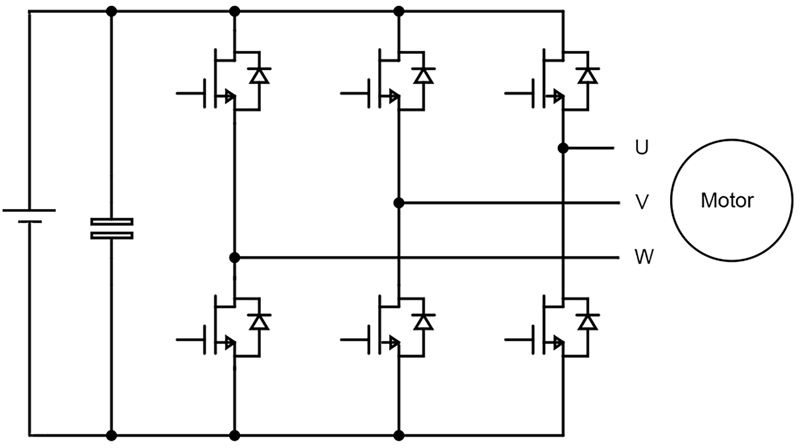
Click image to enlarge
Figure 3: BLDC motors are driven by a bridge arrangement of switches, Quorvo SiC FETs are shown as examples
There are many variables in the implementation of BLDC motor control, including maximum and intermittent torque required, power, speed range, operating voltage, feedback sensor type, their levels and more. These define the voltage and frequency range required of the driver as well as its peak and continuous power rating, including faults and overloads. A controller takes the scaled feedback and status information and through algorithms, provides optimized gate drive signals to the switches, in terms of timing and modulation of a carrier frequency, to set speed and torque.
Control of a BLDC motor
Three-phase BLDC motors can be wound with coils in separate segments with two coils energized at any one time and the third ‘floating’. The floating winding shows a back EMF in a trapezoidal waveform (Figure 4, left) whose zero crossings can be used to determine rotor angular position at low cost and with good accuracy, however, Hall effect sensors allow starting under high load conditions, a response which is difficult to obtain through traditional sensorless algorithms. Mechanically, separated coils is the simplest arrangement but does produce some torque ripple. If the coils are wound distributed around the stator, the back EMF can be made sinusoidal (Figure 4, right) with theoretically no torque ripple. In practice, around 1% is achievable but peak torque and power density are less than with trapezoidal back EMF. This arrangement is a ‘Permanent Magnet Synchronous Motor’ (PMSM) and requires all windings to be energized at any one time so positional information from a floating winding is not available and a separate shaft sensor is usually required. In each case, the PWM drive modulation is arranged to match a trapezoid or sine respectively, for optimum performance.

Click image to enlarge
Figure 4: Back EMF and PWM drive waveforms for BLDC and permanent magnet synchronous motors
The six-step trapezoidal arrangement is easier to implement, is better able to start with high torque and is suitable for very high speed which is useful in power tools, for example. The PMSM in basic form is more expensive to fabricate, starting torque is lower and drive is more complex but speed control is more stable, suiting applications such as ventilation fans. Some schemes start with a trapezoidal drive and switch to sinusoidal as the motor spins up and for best performance, an optical encoder or resolver may be used with a PMSM in place of Hall sensors.
Field Oriented or Vector Control
For optimum performance from a PMSM, ‘vector’ or ‘Field Oriented Control’ (FOC) can be used. This provides full zero-speed torque, smooth operation, fast acceleration/deceleration and better accuracy, for a smaller motor using less energy. Sensors can provide rotor position feedback or ‘sensorless’ schemes use winding current and voltage with a model of the motor characteristics. FOC is complex however, requiring significant digital processing power and a problem is that rotor position information is not available on start-up, so an open-loop initial drive is typically applied until sensors give valid feedback. To provide its superior performance, FOC needs values for field flux linkage and torque which can be derived from rotor position and winding currents. Three-phase winding currents are converted into two-phase equivalents by the ‘Clarke transform’ method, then rotating coordinates are calculated using a ‘Park transform’ along with the rotation angle, and the result represents the parameters to control, flux linkage and torque. These are compared with target values and a compensating feedback signal generated by a Proportional-Integral (PI) controller. This signal is passed through reverse Clarke and Park transform processes to generate drive signals for the switches in the bridge drive circuit, with PWM applied to form sinusoidal currents with RMS values corresponding to the required torque. Figure 5 outlines the scheme.
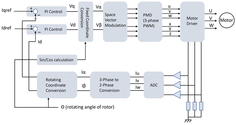
Click image to enlarge
Figure 5. ‘Vector’ or FOC Control of a BLDC motor
BLDC motor control solutions from Qorvo
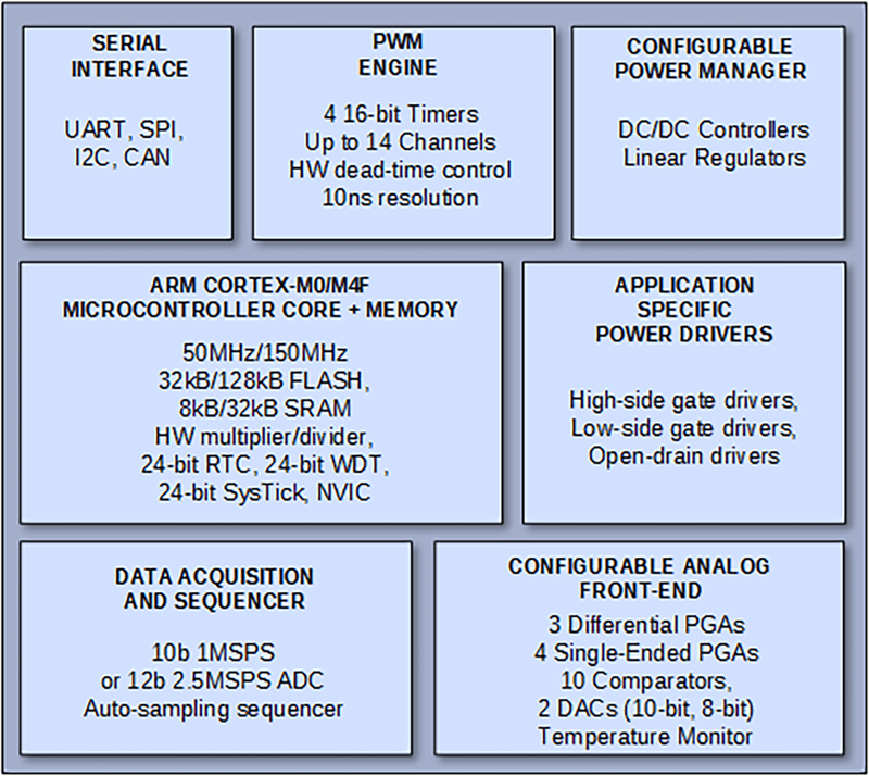
All of the complexity of driving a BLDC motor for best performance, including field-oriented control, can now be implemented in a Power Application Controller (PACTM) from Qorvo in their PAC5xxx series. The single-chip solution includes interfaces for all possible required control parameters and provides drive signals with high peak current capability with up to 600V rating, to cater for battery and rectified mains power rails. Firmware can be remotely configured and updated and an ‘auto-tune’ mode is included to fine-tune operation for a particular motor. The PAC5xxx series is based on either an Arm® Cortex®-M4F running at 150MHz with 32kB SRAM and 128kB flash memory, with a 12-bit 2.5MSPS ADC or the -M0 variant at 50MHz, 8kB SRAM and 32kB flash with a 10-bit, 1MSPS ADC (Figure 6).
Click image to enlarge
Figure 6: The PACTM series BLDC controller from Qorvo
Internal switching and linear regulators are included saving board space and BOM cost. A Configurable Analog Front End (CAFE) includes single-ended and differential programmable gain amplifiers, comparators, digital-to-analog converters, and I/O circuits. This provides inter-connectible and programmable signal sampling, feedback amplification, and sensor monitoring of multiple analog input signals. A low power version, type PAC5285, also integrates power MOSFETs forming a drive bridge for the most compact solution for BLDC applications such as handheld devices and tools. Comprehensive protection, including over-current, over-voltage, under-voltage, and over-temperature is included in all the PACTM family of devices.
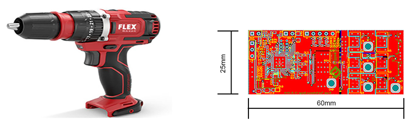
To showcase the capabilities of the controllers, Qorvo offers reference designs for applications such as drone motor drives with the PAC5223 device, a ‘Tiny’ FOC solution just 9mm x 15mm with up to 17A rms output current and an input voltage of 4.5 – 18V. Another reference design, RD5223PT, demonstrates how the PAC5223 can be used in power tools with a PCB size of 60mm x 25mm, designed to fit in the device handle. (Figure 7). A peak current of 25A RMS/300W is supported. For all reference designs, schematics, layout drawings and a BOM are available.
Click image to enlarge
Figure 7: A Qorvo BLDC motor drive reference design for a power tool, 300W peak power
The PAC series of devices from Qorvo are part of an ecosystem of hardware and software support with full data sheets, reference firmware, programming GUIs and guides, application notes and software development kits.
Conclusion
The complexity of drive and sensing systems for BLDC motors has previously been a barrier to their adoption in the cost-sensitive applications of hand tools, small appliances and drones where these motors otherwise offer strong advantages in size, weight, torque and controllability. Now, integrated drive solutions from Qorvo in their PAC device series break the barrier with low-cost, ultra high-performance controllers that, along with comprehensive support, make implementation of end products quick and easy.