Chris Umminger tells PSD about Menlo Micro's new switch technology and how it could transform power electronics applications.
For many years, electromechanical relays have been used to switch large amounts of power. They are capable of handling large amounts of current. However, due to the moving parts used in their construction, their performance can degrade over time. They are relatively slow switching in comparison to other electronics technologies, their contacts can bounce and their operation can cause noise. More recently, solid-state solutions have been introduced. Although they solve some of the drawbacks of electromechanical devices by being quicker, silent and having longer usable lifetimes, they bring their own issues, when passing current, they can heat up, to an extent that often they require additional cooling. Their on-resistance means that they are not as efficient as they could be, and that on-resistance increases with temperature, meaning that the more current they carry, the less efficient they become.
A third way of switching current has recently been developed by Menlo Micro. The new Ideal Switch technique is based on a MEMs-type technology. MEMs are usually fabricated using semiconductor technology and materials, Menlo’s technique employs very similar fabrication processes, with normal semiconductor equipment, but using pure conductors and insulators instead of semiconductor material. The manufacturing process involves only 15 masking steps, and needs no specialized lithography.
Chris Umminger, Senior Director, Power Design Engineering at Menlo Micro, explains, “The Ideal Switch operates through electrostatic actuation, where an electric field generates mechanical force to pull a metal beam down onto contacts. The switch structure is built up using a metal-alloy process on a glass substrate, which is then hermetically sealed with a glass cap to protect from humidity and contaminants. The cap has through-glass vias that bring the electrical connections out to to the surface, which are then connected to a redistribution layer, and to bump bonds for mounting to a PCB, or a lead frame for mounting inside of a package.”
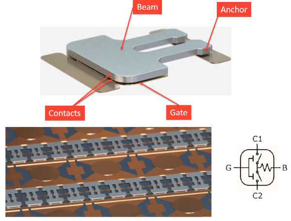
Figure 1 - The Ideal Switch structure. Individual switch elements fit together into an array for higher voltage and current handling.
Each of these individual switching cells measures only 100μm x 100μm and can handle around 200mA and 200V. The switching element has only 0.5mΩ resistance and capacitance of around 10fF between the contact and beam, and 100fF from the contact and gate. By arranging the switch elements in series, additional voltage handling capability can be added, and adding elements in parallel increase current handling capacity. These arrays can then be placed in normal semiconductor packages. The ICs can then be combined together to provide even higher voltage and current handling. A control layer can be added to tailor the devices to particular applications. For example, recently, Menlo launched its new MM5622 system-in-package (SiP) solution which fully integrates a driver, charge pump, and 12 high performance switch channels for RF applications.
Umminger compares the Ideal Switch to electromechanical solutions by saying, “electromechanical devices are slow and have a limited lifetime, maybe 10,000 to 100,000 cycles for cold switching, and significantly less when hot switching. The Ideal Switch can last from 10 million, up to a couple billion cycles, depending on how many switches are in the array. Electromechanical switches are also big and bulky. They use an electromagnetic field and a solenoid to close the contacts, so current is always running through the solenoid to maintain the closed connection. The Ideal Switch uses an electric field, needing 90V to close the switch, but it doesn't draw any current, similar to a power MOSFET. So the energy consumed to hold the switch closed is much less. The Ideal Switch is also around 1000 times faster. Where the electromechanical relay takes roughly 10ms to actuate, the Ideal Switch is around 1000 times faster at 10μs.”
Comparing the Ideal Switch to semiconductor solutions, Umminger continues, “there's a big demand to try to make solid-state switches work in power switching. There, the semiconductor has higher on-resistance per unit area. That higher on-resistance means that the device can't be quite as small, and you have to get rid of more heat. Because the Ideal Switch has lower power loss, it doesn't need a heat sink. Semiconductor technology also has a pretty strong temperature coefficient. Silicon, GaN and SiC all perform well at room temperature, but in power applications, devices are always going to be running hot. The Ideal Switch has the thermal temperature coefficient of a metal. Silicon, GaN and SiC do switch quickly, in the 1 to 10ns range, so those devices are very good for high frequency switching in applications like DC/DC conversion. Power relays, circuit breakers and other similar applications don't need that speed. The Ideal Switch’s 10μs is easily fast enough.”
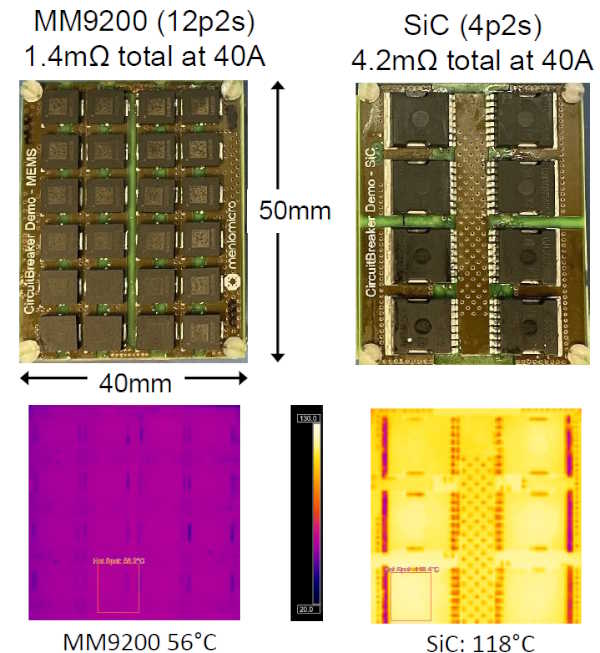
Figure 2 - The compact Ideal Switch solution shows one third of the temperature rise of the SiC solution
The company has developed several product families using the technology, including the MM9200 series for power applications. Used in a 40A array, the MM9200 demonstrated a total resistance of just 1.4mΩ, around a third of the resistance of a similar solid-state solution using SiC technology. This translates to less heat and power losses, with the MM9200 reaching only 56 degrees Celsius at 40A, less than one third of the temperature rise of the SiC solution. The MM9200 also maintained relatively stable resistance across the operating temperature range and can conduct equally well in both directions without the need for additional components. When open, the physical air gap between contacts ensures virtually zero leakage current, unlike semiconductor switches that always have some leakage.
To demonstrate the scalability of the technology to extremely high power levels, Menlo and the Defense Innovation Unit are collaborating to develop a 10,000A, 1,000V circuit breaker for naval propulsion systems. The development will proceed in stages, first scaling to 500V and 100A, then to 1,000V and 125A. The final design will use multiple panels of switches to achieve the full 10,000-amp capacity. Testing so far has shown uniform current distribution across the switch array and minimal temperature rise during operation - critical factors for high-power applications. The switches have also passed rigorous shock and vibration testing, maintaining their state even under harsh conditions.

.jpg)