Challenges of SiC for Automotive Applications

Two of the biggest challenges preventing widespread adoption of SiC diodes and MOSFET devices for traction inverters are high cost and uncertain reliability
(Be sure to check out our PSDcast with ROHM on the same topic here: https://www.powersystemsdesign.com/articles/psdcast-the-formula-e-electric-racing-series/35/13290)
Two of the biggest challenges that are preventing widespread adoption of Silicon Carbide (SiC) diodes and MOSFET devices for traction inverters are high cost and uncertain reliability. Currently, all but a few traction inverters rely on silicon IGBT’s for converting battery voltage into Pulse Width Modulated (PWM) signals for creating the three-phase AC required by traction motors. However, because the IGBTs do not contain a body diode, an external diode must be added across each IGBT to prevent damage due to reverse voltage. Figure 1 shows a schematic of the IGBTs and diodes.
Traditionally, silicon Fast Recovery Diodes (FRD) are used. But even so-called ‘fast recovery’ diodes take a significant amount of time to change from the ON state to the OFF state. This is due to minority carriers that are stored in the drift layer during the conduction phase. The higher the forward current, the greater the reverse current and the longer the recovery time. On the other hand, SiC Schottky Barrier Diodes (SBD) are majority carrier devices and therefore do not have this issue. As a result, switching loss is reduced and overall efficiency increased. Figure 2 shows a comparison of the behavior of a Fast-Recovery Diode vs. SiC SBD at various forward currents prior to reversing the current.

Click image to enlarge
Figure 2. Reverse Recovery Time vs. Forward Current for Fast Recovery Diode vs. SiC Diode
As an example of improvement, the traction inverter used in Season 3 of Formula E’s electric car racing series replaced the conventional silicon diodes with ROHM SiC devices, resulting in a 1.7% improvement in efficiency.
Despite their higher cost, another area where SiC Schottky Barrier Diodes have found widespread acceptance is in Power Factor Correction (PFC) circuitry used for onboard vehicle chargers. Figure 3 shows a typical onboard charger topology.

Click image to enlarge
Figure 3. Typical Onboard Charger Topology
By using SiC Schottky barrier diodes instead of silicon diodes for DB1 and DB2,efficiency improvements of 1% - 2% can be realized. Similar circuitry is used for both Level 1 (120VAC) and Level 2 (230VAC) charger inputs. Since this application involves a transformer, as the switching frequency increases the size of the magnetics decreases. For this reason, SiC MOSFETS and even GaN are finding their way into switching devices used for charging applications.
Wireless charging is another area where low switching losses are important. Switching frequencies for wireless vehicle charging are typically range from 70 kHz to 100 kHz or more. SAE Standard TIR J2954 recommends a charging frequency of 81.4 kHz-90 kHz at power levels from 3.7 kW to 22 kW. For power levels above about 12 kW it makes sense to use three-phase 480 VAC input which is commonly found at most businesses in the US. This application calls for switches rated at 1200V, but getting traditional silicon MOSFETs with low enough on-resistance can be expensive. SiC MOSFET pricing becomes much more competitive at this power level and so many customers often select SiC MOSFETs for such applications.
SiC MOSFETs
One strong point for considering SiC MOSFETs as opposed to IGBTs is their reduced switching losses that provide the opportunity for faster PWM switching speeds. This is especially true for turn-off where IGBTs commonly have a ‘tail’ of current at the end which greatly increases turn-off loss.
Unfortunately, faster SiC PWM switching speeds generate waveforms prone to overshoot and ringing, which can be detrimental to the insulation used in the traction motor windings. Faster switching (high dV/dT) can create a small breakdown called partial discharge in any air-filled voids in the insulation material. Repeated partial discharge breakdowns will gradually destroy the insulation. Therefore other improvements/countermeasures must be used to achieve the advantage of higher switching speed.
One example of the successful transition from IGBTs to SiC devices is the traction inverter used in Formula E electric cars for Season 4. Figure 4 shows the significant size and weight reduction – along with increased output power – made available by changing to full-SiC modules.

Click image to enlarge
Figure 4. Formula E Traction Inverter Improvements
Another example of improved efficiency comes from Oak Ridge National Laboratories (ORNL). From their news release: “ORNL collaborated with partners to build the industry’s first silicon insulated-gate bipolar transistor–SiC Schottky diode hybrid 55 kW inverter. The WBG SiC materials enable the inverter to perform with up to 30% efficiency improvement compared to an all-silicon module.”
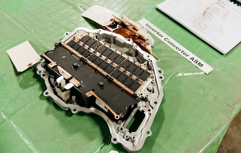
Although many US car manufacturers are investigating SiC MOSFETs for Traction Drives, so far the only company to use them is Tesla. According to a UBS report, the Tesla Model 3 Traction Inverter uses STMicro SiC MOSFETs. Rather than buying a complete ‘Power Module’ they decided to fabricate their own by paralleling a number of smaller devices. It appears that each leg of the switches (shown in Figure 1) consists of eight devices in parallel (4 x 2 die per package) as shown in Figure 5.
Click image to enlarge
Figure 5. Tesla Model 3 Traction Inverter
Other automotive applications for SiC MOSFETs include air conditioning compressor motors, water pumps, and DC/DC converters. Both EVs and HEVs still use 12VDC for operating devices such as infotainment systems, door locks, fans, onboard computers, and lighting. Consequently, EVs/HEVs require a DC/DC converter to step down the battery voltage (48V or more) to 12V. This normally consists of a transformer isolated converter with a power level of around 1-2 kW. Since the size of the transformer is reduced with higher frequency switching, it makes sense to use either GaN or SiC MOSFETs for this application.
For an EV to provide air conditioning, since there is no gasoline engine to turn the compressor, an electrical drive is necessary to run the compressor motor (from a circuit like that used for the traction inverter). And because the compressor motor draws a significant amount of power, efficiency is an important factor, so utilizing SiC MOSFETs can improve results.
Reliability
SiC MOSFET failure modes are different than IGBTs. Types of failures include:
· Threshold voltage shift
· Increased ON resistance
· Increased forward voltage drop of the body diode
· Breakdown voltage
The most popular automotive testing specification for transistors is AEC-Q101-Rev D1: ‘Failure Mechanism Based Stress Test Qualification for Discrete Semiconductors in Automotive Applications’. However, this test specification does not address complete ‘Power Module’ testing. This has led many manufacturers to come up with their own series of testing specifically for power modules. For example, Infineon has stated, “Due to a missing standardization, hybrid systems of different car manufacturer are so dissimilar that a comparison between them is rather impossible.”
Types of testing called out in AECQ-101 relevant to SiC MOSFETs are:
· High Temperature Reverse Bias (HTRB)
· High Temperature Gate Bias (HTGB)
· Temperature Cycling (TC)
· High Humidity High Temperature Reverse Bias (H3TRB)
For SiC devices, additional testing such as Body Diode Reliability (continuous and pulsed), Dynamic Gate Stress testing, extended Thermal Cycling tests (TCY) and Power Cycling Lifetime tests are often necessary to ensure device quality.
Conclusion
SiC MOSFETs and diodes are finding increased acceptance for a variety of applications in both EVs and HEVs. And when field reliability has been demonstrated to be as good as conventional IGBTs and silicon MOSFETS – and as wafer size increases and the price continues to fall - SiC MOSFETS are sure to find their way into more and more traction inverters as well.