It is important to have the right device to protect the things that are important and valuable to us
A good insurance plan is not just good to know about, in many aspects of daily life it is indispensable. In the case of Class X and Class Y capacitors, they are required to function reliably in all parts of mains-connected electrical devices, as they offer a form of insurance — we expect them to protect things that are important and valuable to us. X capacitors protect the electrical device itself, whereas Y capacitors protect the user by capturing smaller, still acceptable stray currents in case of malfunction.
Going broke saving money
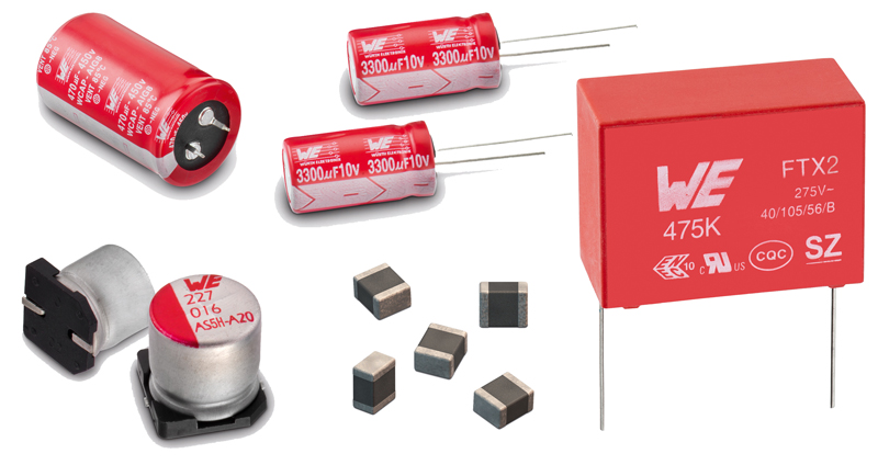
False economies here can leave a lasting impression. On average, these components are required to reliably filter over 1,000 noise spikes from the mains per year. Cheaply made capacitors with unevenly metallized plastic film, inadequate safety gaps or weak pin contact on the Schoop layer, to name just a few potential issues, can sharply reduce the component's service life, not to mention being a major safety risk that could start a fire in the event of failure. X and Y capacitors for reliable circuit protection are available on the market in different configurations (SMD, THD) and designs. Look for official certification under applicable standards by VDE/TÜV and UL to ensure the safety of your application (see Figure 1).
Click image to enlarge
Figure 1: X and Y capacitors for reliable circuit protection are available on the market in different configurations (SMD, THD) and designs
Dealing with stress and impact
Multilayer ceramic capacitors (MLCCs) generally possess a highly-limited resistance to mechanical stress. When mechanical stress occurs, MLCCs are often the weakest link in the chain of susceptible components in your application. In addition, capacitors are at risk from drops, and not only in mobile devices. Even in production, poorly laid out design specifications, with ceramic elements placed too close to broken or cut edges of circuit boards or fasteners, can lead to damaged components.
As circuits grow ever smaller, developers often find themselves shaving the mechanical safety tolerances of their designs ever closer. The result is cracks in the ceramic body of the MLCC at the solder point. If these flaws are not detected in final electrical testing (ICT), since mechanical stresses can create an intermittent electrical contact, discovering a sporadic failure can require painstaking and costly troubleshooting.
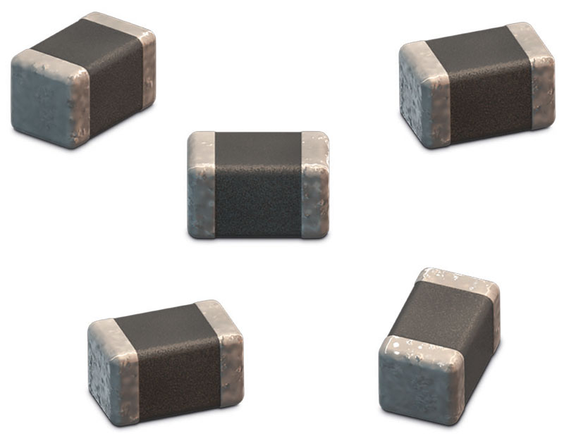
Because multilayer ceramic capacitors are susceptible to mechanical stresses, manufacturers offer various solutions that can significantly improve their durability and help minimize the risk of a short circuit and its consequences (see Figure 2). One such option is introducing a polymer layer between the ceramic body and the MLCC's terminals, which can multiply the component's robustness against mechanical stresses by a large factor. Because of their more complex construction, capacitors like these are at a cost disadvantage compared to conventional components, but in many cases this is more than offset by their safety advantages.
Click image to enlarge
Figure 2: Manufacturers offer various solutions that can significantly improve system durability and help minimize risk
Other mechanical solutions include "open mode" and "floating electrode" MLCC designs. Where the solution described above is designed to prevent mechanical damage to the capacitor, construction modifications in the latter types are designed to prevent a short circuit in case of failure. In open-mode capacitors, the internal active area is decreased so that a crack does not result in a direct short circuit between layers. Floating electrode capacitors use a serial circuit configuration as already successfully implemented in film capacitors. A break at one of the MLCC's contact points results only in a local short there.
The requirements for components in various types of high-frequency signal transmission processes are particularly stringent. One of the most important criteria here is minimizing the MLCC's parasitic inductance, which in turn raises the component's resonant frequency.
One very effective design modification of this sort is offered by reverse-geometry capacitors (RGCs), i.e. MLCCs whose terminals are placed on the long rather than the short side of the component. This achieves a sharp reduction in the length of the signal path through the capacitor, and thus significantly lowers inductive behavior. In addition to keeping the MLCC's terminals as short as possible in the circuit board design, this component geometry makes it possible to reduce the capacitor's inductance by over 50%.
Aging
Despite all their advantages, both technical and economic, ceramic capacitors also have various disadvantages. It is essential to keep these in mind in circuit design so that the initial advantages are not transformed into disadvantages that may be difficult to overcome. MLCCs are theoretically available in four classes, of which only classes 1 to 3 are relevant in practice. There are major technical differences among them.
Aging behavior is one, if not the essential factor influencing the choice of component. Only those MLCCs categorized in Class 1 and designated NP0 or C0G show practically no aging behavior. The smallest tolerances (<1 percent or 0.1 pF) and the lack of voltage-dependent change in capacitance offer the greatest available precision during the whole application lifetime.
It is crucial for developers to keep this point in mind: by comparison, the ceramics used in Class 2, most commonly X5R and X7R, can display a significant drop in capacitance (greater than 30%) after only 1,000 hours of operation. Similar behavior occurs when Class 2 ceramics are operated at higher than half of the designated rated voltage.
Aluminum electrolytic capacitors, heat, and stress
Conventional aluminum electrolytic capacitors are filled during the manufacturing process with a liquid electrolyte that actually needed to ensure the flow of electrons during operation. This fact is a key factor in the aging process as such and in the actual performance of these components. If manufacturing process reliability in combination with the materials used have a decisive impact on the quality of the capacitor, the circuit design has at least a great effect on the durability of the application.
A compromise is often required between keeping the connection of the electrolytic capacitor short, especially in the power element of a circuit, and the waste heat produced there, which accelerates the component's aging. Aluminum electrolytic capacitors placed too close to a heat sink in a power supply or heat flow from a fan can age extremely rapidly in relation to other components. Not only does the evaporation of the electrolyte (and the resulting drastic loss of capacitance) practically guarantee a failure, the now-dry capacitor is a significant safety risk and may even disintegrate explosively.
Aluminum electrolytic capacitors can attain large volumes due to the size of the capacitance value required. Those with a snap-in design have highly durable solder connections. Often the bent contacts are not only required to withstand large amounts of energy, but also to connect the capacitor reliably to the circuit board. The mass of these components can range from a few grams to far over 100 grams.
Depending on the variant and application, capacitors can be protected from vibrations and other mechanical stresses by attaching additional dummy contacts in addition to the two solder contacts between the capacitor and the board. These give the component greatly enhanced stability against vibrations. Despite this enhanced safety, the capacitor should not be used as a brace for fitted components, as the tensile forces through the connector pins act directly on the aluminum foil of the component, where they can cause microscopic damage and a sharply reduced service life.
An alternative: aluminum-polymer capacitors
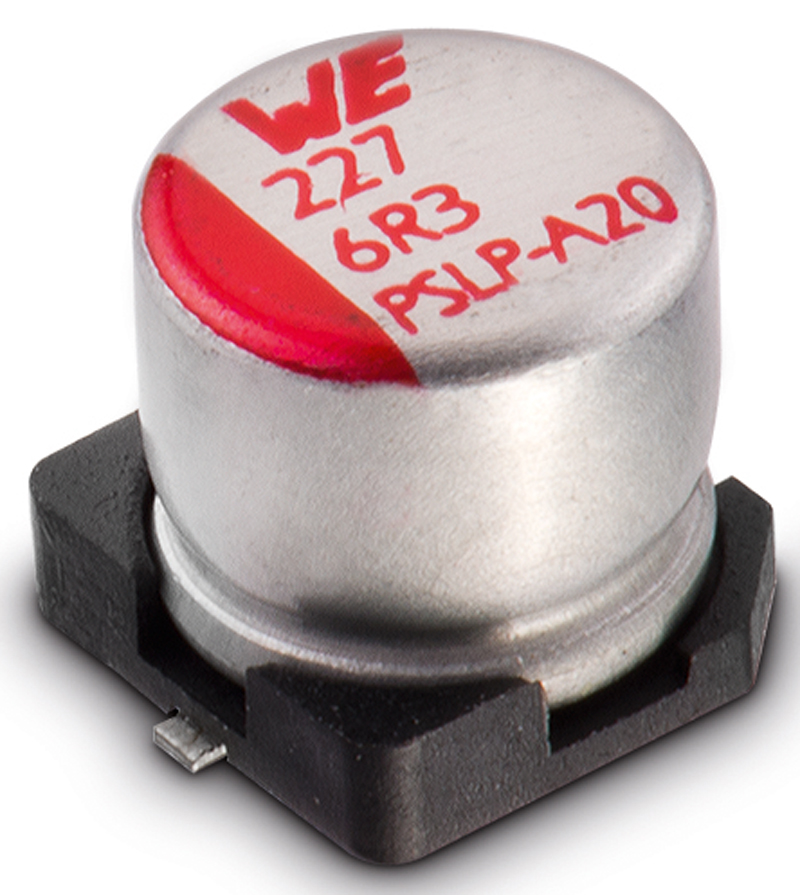
The circuit engineering requirements for passive components are becoming ever more demanding. For high-capacitance aluminum capacitors in particular, the key factor is the call for ever-lower ESR values, and the associated ripple current rating (see Figure 3).
Click image to enlarge
Figure 3: The appeal of aluminum polymer capacitors on the market has been growing steadily for the past several years
While choices were few when these components first reached the market, especially for voltages below 25 V, the range of available options on the market has been growing rapidly. Development has moved in several different directions, with SMD and THD configurations available.
The evolution of ESR values is tending towards a few milliohm (≤10 mΩ), while in wired components voltages of up to 100 V are already available in series production. There is a strong push in aluminum polymer capacitor development. Once used more in consumer products, these components will increasingly make their way into industrial applications as well.
In the future, conventional aluminum electrolytic capacitors with an added wet electrolyte will see increasing competition from dry aluminum polymer capacitors. The main difference between them is also what is responsible for the aluminum-polymer capacitor's significantly longer service life.
Where the wet electrolyte in the traditional type tends to dry out over time, leading to an increased risk of failure, solid polymer capacitors can last up to ten times as long. Due to their design these components have very low ESR values, resulting in very low intrinsic heat generation in combination with the ripple current impinging on the circuit.
Conventional aluminum electrolytic capacitors also have advantages when compared to polymer capacitors. Whereas voltages of up to 600 V are currently technically possible with the electrolytic type, aluminum polymer capacitors are only available on the market in series production up to 100 V. Aluminum electrolytic capacitors also offer smaller leakage currents and lower prices than aluminum polymer capacitors, although the price difference is reversed when the latter's much longer expected service life is considered.
Moisture-proof foil capacitors
Metallized film capacitors, in which the charge is stored in a metal layer applied to a plastic film as a winding element or in a layered structure, are significantly influenced by two physical measures. Temperature and moisture represent major challenges for capacitors of this type.
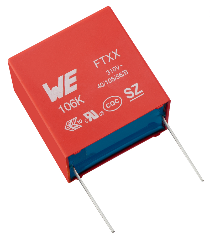
Along with numerous variants, the so-called "85/85 test", in which a component is tested for up to 1000 hours at a temperature of 85°C and relative humidity of 85%, can be a highly effective procedure for determining the quality of construction and materials used (see Figure 4). If the seal is insufficiently resistant to temperature fluctuations, moisture can penetrate the capacitor more quickly, leading to a chain reaction in which the insulation resistance declines, voltage spikes damage the metallization and a high influx of energy ultimately destroys the component altogether.
Click image to enlarge
Figure 4: Proper testing can be a highly effective procedure for determining the quality of construction and materials used in film capacitors
Moisture-resistant (or THB, for "thermal humidity bias") film capacitors are available on the market, although their modified design and the special materials used generally put them at a price disadvantage compared to standard versions. The higher price is only a disadvantage at first glance, however, as it is outweighed over the long term by performance gains.


