Electronic components in household and professional
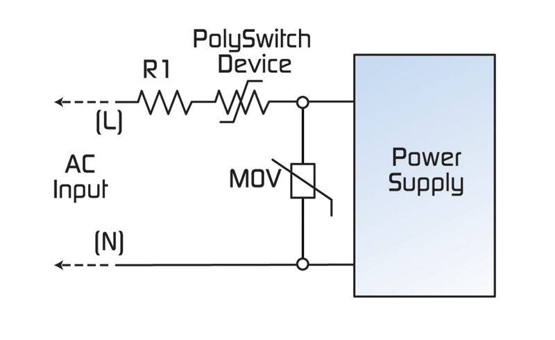
Figure 1: Typical circuit protection design for switch-mode power supplies
The power supplies, relays and other electronic components found in household and professional-grade appliances can benefit from the application of resettable overcurrent protection. Polymeric positive temperature coefficient (PPTC) devices offer low resistance and are compatibly sized with fuse solutions. Like traditional fuses, they limit the flow of dangerously high current during fault conditions. The PPTC device, however, resets itself after the fault is removed and power to the circuit is cycled, obviating the need to replace a blown fuse. Protecting increasingly sophisticated and complex control boards from misconnection, power surges or short circuit damage is also of particular concern to the equipment manufacturer. Although appliance transformers, their enclosures and connections are capable of withstanding higher voltage transients, the use of sensitive solid-state devices on the board necessitates improved overcurrent and overtemperature control. A coordinated circuit protection strategy can help protect equipment from damage caused by excessive currents during a fault or overload condition, as well as voltage spikes or exposure to steady-state overvoltage conditions. SMPS Design Considerations Switch-mode power supplies (SMPS) offer the size, weight, and energy-saving advantages required for consumer electronics and have continued to replace linear-regulators in many applications, including white goods. However, because SMPS lack the inherent resistance of prior generation designs, they often require more robust circuit protection. PPTC overcurrent protection devices can help manufacturers meet UL60950-1/LPS (Limited Power Source) requirements for SMPS and improve equipment safety and reliability. While these devices cannot prevent a fault from occurring, they respond quickly, limiting current to a safe level to help prevent collateral damage to downstream components. Additionally, the small form factor of PPTC devices makes them easy to use in space-constrained applications. The PPTC device has a low-resistance value under normal operating currents. In the event of an overcurrent condition the device "trips" into a high-resistance state. This increased resistance helps protect the equipment in the circuit by reducing the amount of current that can flow under the fault condition to a low, steady-state level. The device remains in its latched position until the fault is cleared. Once power to the circuit is cycled, the PPTC device resets and allows current flow to resume, restoring the circuit to normal operation. As shown in Figure 1, a PolySwitch™ PPTC device can be installed in series with the power input to help protect against damage resulting from electrical shorts, overloaded circuits or customer misuse. Additionally, a Metal Oxide Varistor (MOV) placed across the input helps provide overvoltage protection. The PolySwitch device may also be placed after the MOV. Many equipment manufacturers prefer protection circuits combining resettable PPTC devices with upstream fail-safe protection. In this example, R1 is a ballast resistor used in combination with the protection circuit.
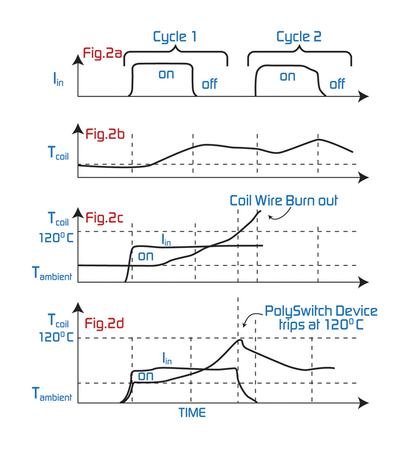
Solenoid Design Considerations A solenoid is an electromagnetic device consisting of a coil assembly, frame, armature, and backstop. The coil assembly and backstop are mechanically secured within the frame and the armature is inserted into the assembly. When the coil is excited with current, a magnetomotive force is created, causing the plunger to be pulled into the coil and seat on the backstop. Once the solenoid is energized, the end of travel is detected by a sensor. The sensor then feeds back the position of the armature to the system electronics, turning off the power to the solenoid. Should the sensor fail, causing the armature not to pull in, the intermittent solenoid will generate excessive heat and may fail. Installing a PPTC device in combination with an MOV on the primary side of the AC input can help protect against damage caused by overcurrent and overvoltage faults. Unlike a single-use fuse, the resettable PPTC device also helps protect against damage resulting from conditions where faults may cause a rise in temperature with only a slight increase in current draw. Certain overload conditions may cause the MOV to remain in a clamped state where it will continue to conduct current. This may eventually result in an overtemperature failure of the device. Placing the PPTC device in series with and in close thermal proximity to the MOV can help protect that MOV in extended overload conditions - by transferring heat to the PPTC device. This causes the PPTC device to trip faster, limiting the current through the MOV. This technique lets designers leverage the temperature response of the PPTC device and replace other thermal protection elements in the circuit. Not only does the PPTC device perform dual functions in this case, it also provides a fully resettable solution. Probably the most common cause of solenoid failure is mechanical blockage. This can occur when the solenoid becomes contaminated with dirt or debris that lodges between the armature and the inside of the coil, blocking proper movement. Other problems include misalignment, broken springs or an opposing force. Any of these conditions can cause constant current to be applied to the solenoid, increasing coil temperature and ultimately burning the coil insulation and wires. As shown in Figures 2a and 2b, during normal conditions, the coil temperature increases each time the solenoid is cycled. Figure 2c illustrates how an overtemperature fault may cause the coil windings to burn out. Figure 2d shows how a PolySwitch device inserted in the circuit will trip at approximately 120°C, limiting IIN so that the coil temperature gradually drops and helps prevent damage to the coil. Figure 2: PolySwitch device helps prevent overcurrent/overtemperature damage by limiting current to coil. Any of these conditions can cause constant current to be applied to the solenoid, increasing coil temperature and ultimately burning the coil insulation and wires. As shown in Figures 2a and 2b, during normal conditions, the coil temperature increases each time the solenoid is cycled. Figure 2c illustrates how an overtemperature fault may cause the coil windings to burn out. Figure 2d shows how a PolySwitch device inserted in the circuit will trip at approximately 120°C, limiting IIN so that the coil temperature gradually drops and helps prevent damage to the coil.
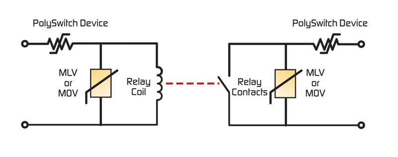
Relay Design Considerations Relays are frequently used in consumer electronics to control high currents and voltages with lower signal levels, or to switch currents that must be isolated from the control circuit. A relay's most basic components are its coil, armature, and contacts. When the relay is put into a circuit, the current from that circuit induces a magnetic field in the relay coil. The magnetic field then affects the armature in such a fashion that it causes the contacts to make or break the part of the circuit that is attached to the relay output. Relay damage can result from excessive voltage or current. A common problem can occur when a relay interrupts current to an inductive load and causes a voltage spike. If the voltage spike is severe enough, to exceed the relay's contact voltage rating, the contacts can be damaged (V = Ldi/dt). This damage may occur suddenly or slowly, over many years of operation. Additionally, excessive current through the relay contacts can cause damage when the contacts open and the current is interrupted. Excessive currents and voltages can also damage the relay coil. If a relay coil is designed to be energized for only a short duration in normal operation, normal operating current may eventually harm the coil if it is accidentally energized for an extended period of time. Figure 3 shows a typical relay protection circuit. A PolySwitch device is placed in series with the relay coil to limit the current to the relay in case of a fault or accidental overload. This figure also shows a PolySwitch device in series with the relay contacts. It is important to choose a PPTC device with a voltage rating equal to or greater than the maximum expected voltage. The device must also have a hold current equal to or greater than the maximum steady-state current in normal operation. Additionally, the maximum ambient temperature must be taken into account because the hold current decreases as the ambient temperature increases. Figure 3 also shows an MOV or MLV in parallel with the relay contacts. These devices are rated according to voltage and maximum surge current. It is important to select a device that will not conduct significant current at the normal peak voltage. MOV specifications include a maximum allowable AC or DC voltage. Each MOV and MLV device also has a maximum surge-current rating. The usual standard for rating surge currents uses an 8/20 microsecond wave shape (i.e., an 8-microsecond rise time, and a 20-microsecond delay time to half the peak value). As the varistor size increases, the 8/20 microsecond surge current rating increases. An MOV or MLV can also be used in parallel with the relay coil, as shown in Figure 3. Summary Coordinated overvoltage/overcurrent circuit protection can help designers reduce component count, provide a safe and reliable product, comply with regulatory agency requirements and reduce warranty and repair costs. PPTC devices offer resettable functionality and low resistance in the circuit. They are rated to 240 VAC, permitting maximum voltages of up to 265 VAC and can be installed in the AC input lines. MOV and MLV devices help manufacturers meet a number of safety agency requirements, and provide high current-handling and energy absorption capability as well as fast response to overvoltage transients. www.circuitprotection.com