Considerations for small solar power systems
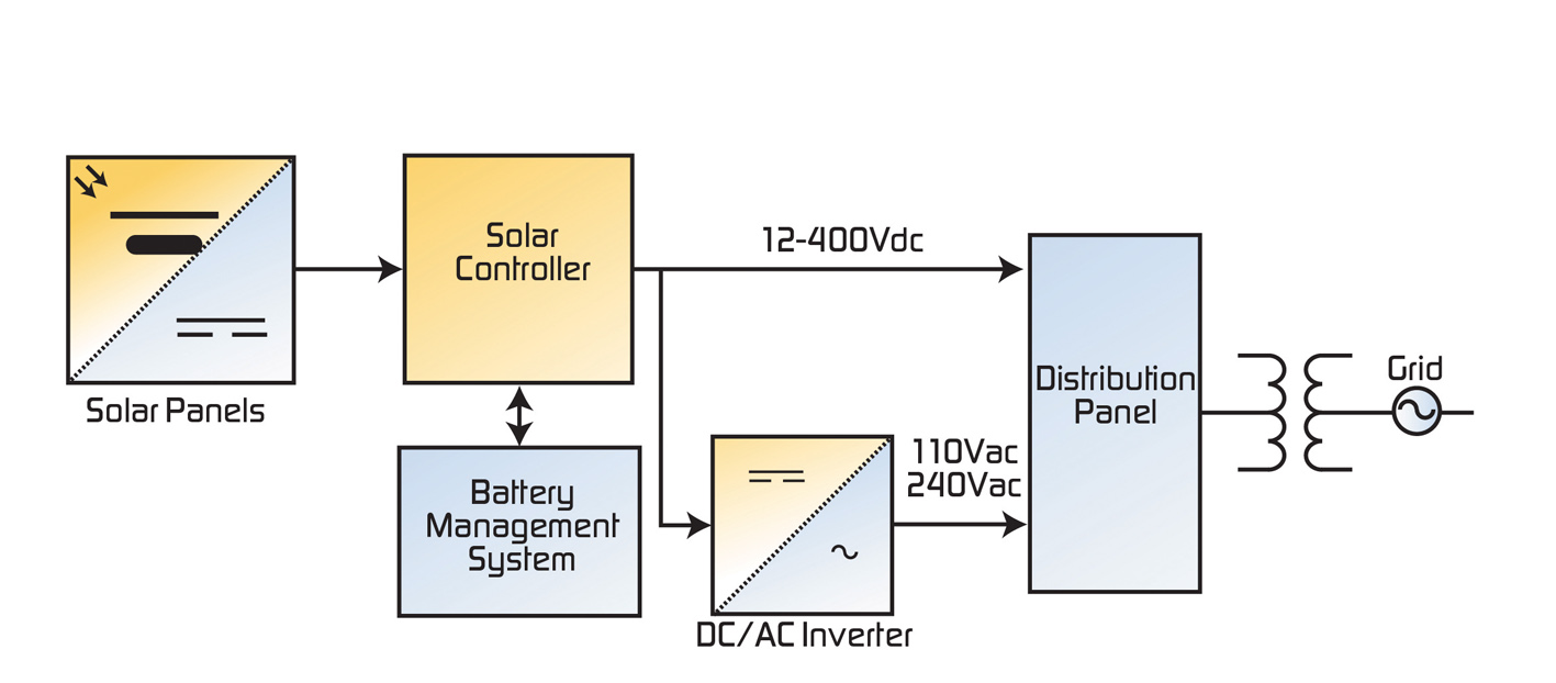
Figure 1: Typical solar power system diagram
Increasing demand for clean electrical power has led to a focus on renewable energy sources such as solar power. Solar power systems are independent power generation systems meant to power an individual structure or an entire community. The solar power block diagram in Figure 1 describes a typical system of solar panels, a controller, energy storage and an inverter for conversion of DC to AC, and shows how the solar power generator can be connected to the power grid if desired.
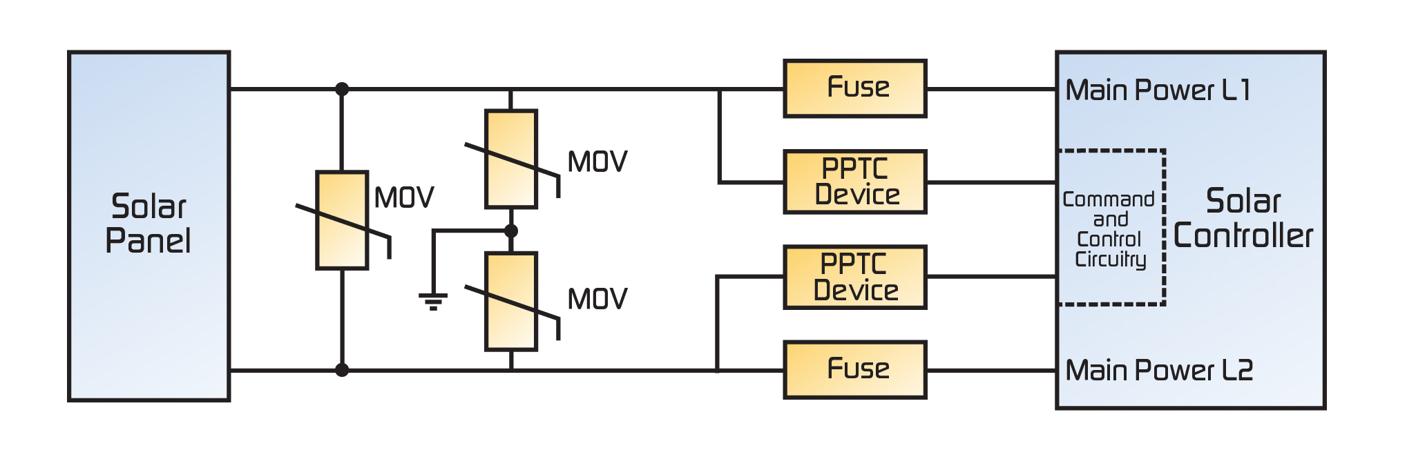
Lightning Protection To maximize light exposure over the solar panels they are usually installed in open fields or in elevated locations (e.g., rooftops of buildings). These installations can make solar power generation systems vulnerable to transients, such as ring-wave and lightning, as well as coupled transients from adjacent cables like power/control lines in the same conduit. In compliance with the electrical environment category of IEC61000-4-5, the power connect cabling out of the solar panel is a Class 4 subset of the IEC61000-4-5. Protection levels of Class 4 electrical systems are 2kV line-to-line and 4kV line-to-ground, although adopting 6kV protection levels is recommended. The surge-handling capacity of overvoltage protection devices is particularly important in these applications. An effective, coordinated protection solution helps minimize downtime, an important consideration since solar power systems usually consist of unattended operations with long maintenance and service life requirements. The cable of each solar panel in the solar power system is first connected to the header box of the solar system controller. Figure 2 illustrates an overvoltage protection design with MOV (metal oxide varistor) overvoltage protection devices applied to the input terminals of the header box and controller. For solar applications with higher voltage and reliability requirements, gas discharge tubes (GDTs) connected in series with MOVs help provide a greater level of protection - especially for cabling running outside of premises. For lower power systems with voltages less than 48VDC, GDTs can be used alone for overvoltage protection. Consideration must also be made for failure modes of overvoltage devices from follow-on current. A coordinated overcurrent/overvoltage protection scheme can help improve system reliability in the case of overvoltage device failure. The resettable polymeric positive temperature coefficient (PPTC) devices shown in the coordinated solution can be used for AC or DC powered loads in the system.
For the DC load of solar power systems, the circuit design in Figure 2 may also be applied for lightning protection. For lightning protection of AC loads (i.e., output of inverter) the protection circuit design shown in Figure 3 can be utilized.
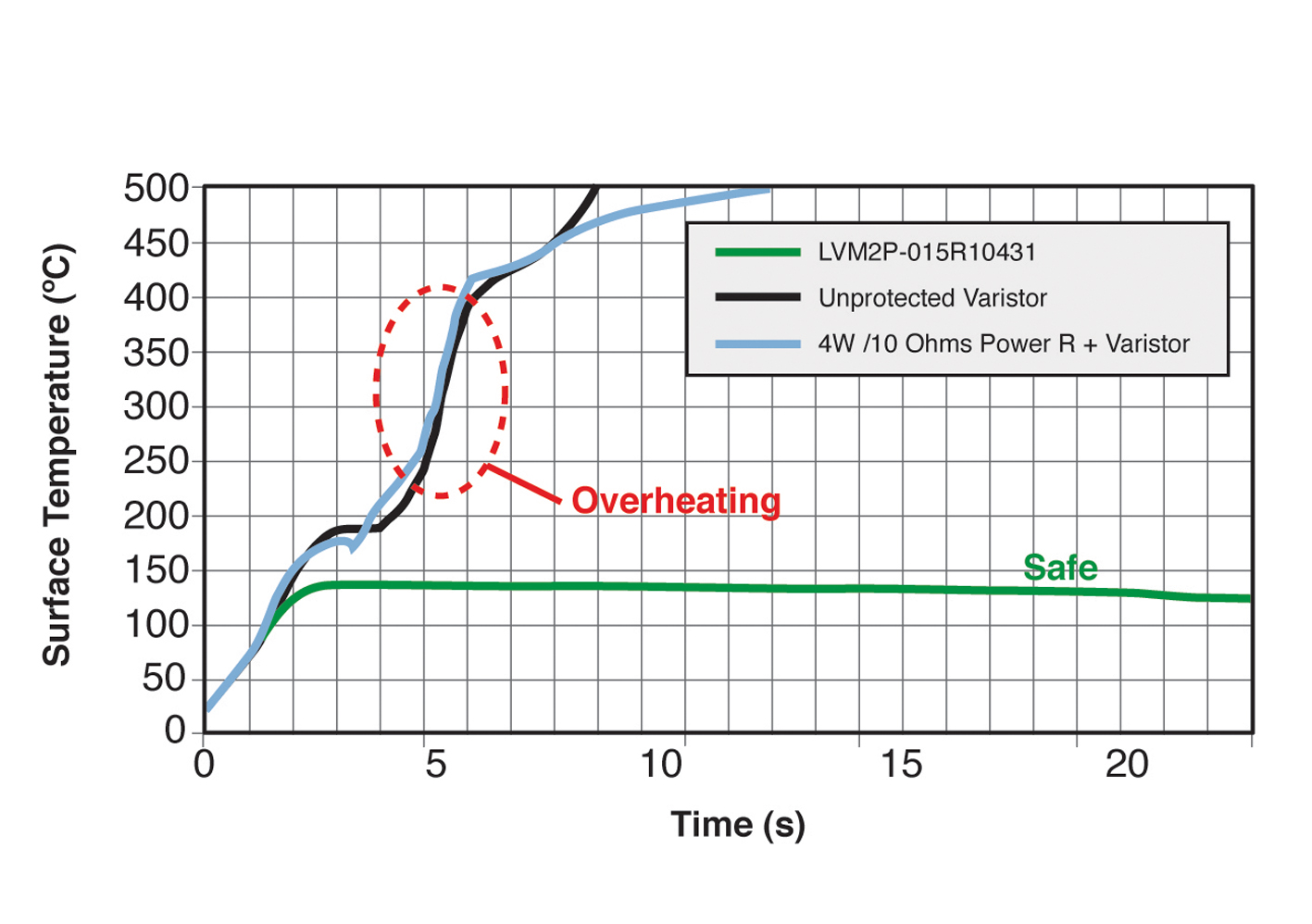
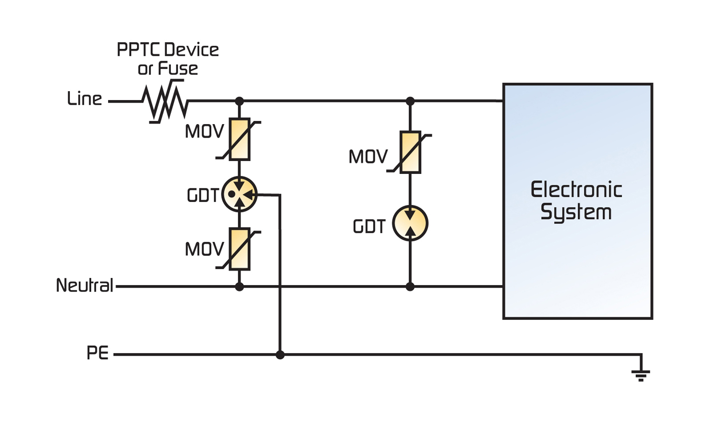
Controller and inverter protection The power output generated by the solar panels can vary depending on light levels received due to clouds or other types of shading effects. One example is when the sun traverses the horizon and shade from trees or structures prevent light from striking the entire array, causing droops in power levels received by the controllers and inverters. Controllers and inverters are susceptible to many types of transients. Electrostatic discharge (ESD) sources include human, open air or a phenomenon of transients that are generated from the glass of the solar panels and discharged into the controller and inverters. Coupled transients like EFT (electrical fast transient) and ringwave, and lightning, whether by direct or indirect (close proximity) hits, can also generate transients. Communications ports on controllers and inverters are susceptible to these transients. Protecting the controller and inverter and their communications ports from overvoltage transients can be accomplished with the 2Pro device, which combines a PPTC overcurrent component with an MOV into one thermally protected device. This device helps to provide resettable current limiting for overcurrent conditions and voltage clamping during overvoltage events. Under normal operating conditions the AC line voltage applied to an MOV is not expected to exceed the device's maximum AC root mean voltage (VACRMS) rating and, provided that the transient energy does not exceed the MOV's maximum rating, short-duration transient events are clamped to a suitable voltage level. However, a sustained abnormal overvoltage/limited current condition may cause the MOV to go into thermal runaway. Standard unprotected MOVs are typically rated to 275VACRMS for a universal input voltage range. In a loss of neutral condition they may overheat with negative consequences, even if a fuse or power resistor is used upstream. In a worst case scenario, as shown in Figure 1, a voltage of 400VAC instead of 230VAC, derived from a loss of neutral, is applied. In such an unlimited current condition, the unprotected MOV will first fall to low impedance of a few ohms, but due to the high amount of energy present it may rupture. If there are devices placed on the AC line return path to limit current flow these may also overheat due to the failure of the MOV. Figure 4 illustrates the effects of these abnormal overvoltage conditions on three devices or a combination of devices:
- 2Pro device (TE's LVM2P-015R10431 device)
- Single MOV (10mm, 275 VRMS - TE's ROV10-431K device)
- MOV/4W with power resistor (10 ohms)