Author:
By: Zeke Pietsch, Customer Success Manager, EA Elektro-Automatik, Inc.
Date
07/31/2021
 PDF
PDF
Click image to enlarge
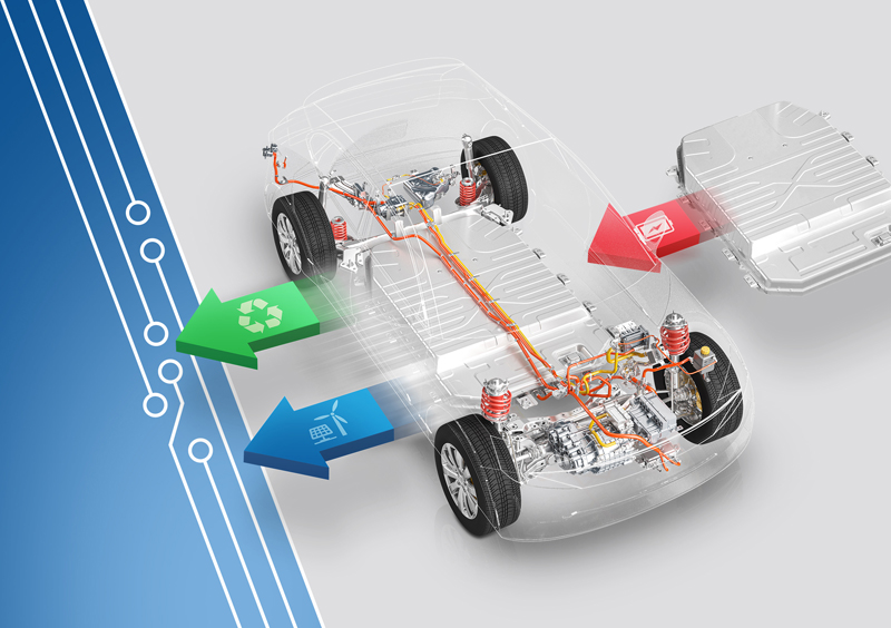
Figure 1 here
Figure 1. E-Mobility: Sustainable battery recycling with EA Elektro-Automatik
Fuel cells have found applications in material handling vehicles, delivery vehicles, long-haul trucks, and use as backup power systems. Government initiatives, economic incentives, and new applications are resulting in a market growth rate exceeding 30%.
An individual fuel cell generates under 2V of output, so practical fuel cells are assemblies or stacks of multiple cells. Fuel cells can output up to125kW for vehicles; and, the largest fuel cells, used for backup power, can have a capacity of 1.5MW and operate at 900V. As fuel cell technology is improved, manufacturers will be designing fuel cell stacks with higher power and higher voltage ratings.
With such high power capacity, testing fuel cell stacks is essential to ensure that they have a minimum specified efficiency, are safe, and have the required operating life. EA Elektro-Automatik regenerative electronic loads and bidirectional power supplies with built-in regenerative loads have high input and output capacity to test fuel cell stacks. Electronic loads are available in models with a 30kW capacity and voltage output of 2000V. Current capacity can be1000 A. Up to 64 loads can be paralleled to enable testing fuel cells with power levels up to 1.92 MW. The same power handling and parallel instrument capacity exists in the bidirectional power supplies for either sourcing or sinking power.
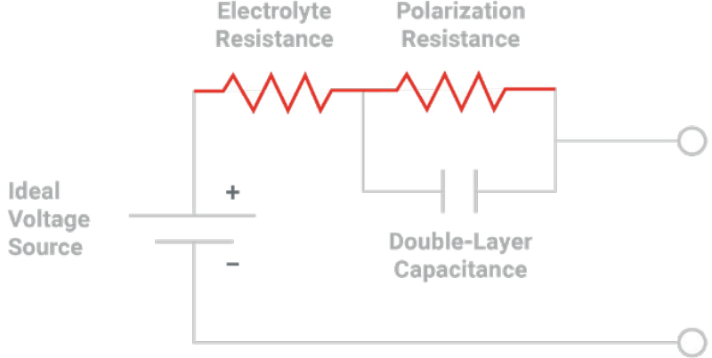
Figure 2 Shows a simplified circuit model for a fuel cell. The most important parameter of a fuel cell is its resistive component.The electrolyte resistance is the main contributor to the total resistance of the fuel cell. The polarization resistance models the reaction equivalent resistance, and the double layer capacitance models the anode-electrolyte-cathode interfaces.The lower the total resistance of the fuel cell is, the lower is its power loss and its efficiency is higher. With power generation of kW to MW, an excessively high total resistance can prevent a fuel cell stack from outputting its maximum rated power.
The difficulty with measuring the resistance of the fuel cell is due to fact that the cell voltage source cannot be isolated from the resistive components as the circuit model might suggest. Rather than employing a conventional DC resistance measurement, the measurement of fuel cell resistance requires an AC measurement or a pseudo-AC measurement. In either case, a perturbation, a ΔI, created by the load results in a ΔV(ΔU) across the fuel cell; andfuelcellresistance,R=ΔV (ΔU) /ΔI.
Click image to enlarge
Figure 2. Simplified model of a fuel cell
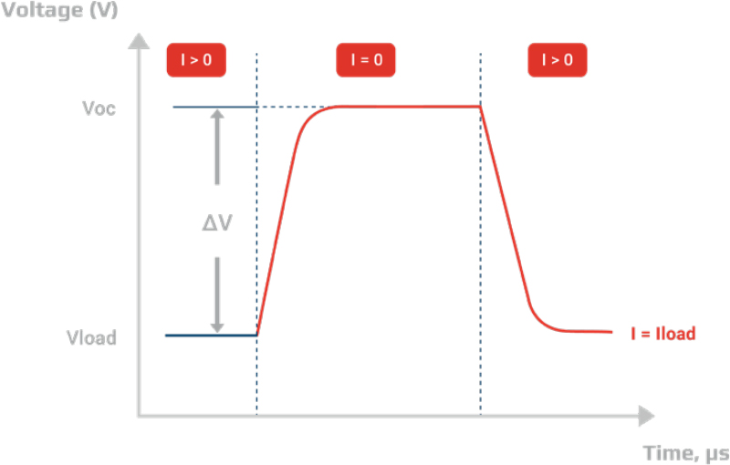
The pseudo-AC measurement is known as the current interrupt method. This method, as the name describes, creates a ΔI by instantaneously switching the load current from a steady state value to 0A.The fuel cell voltage rises to its open circuit voltage from the voltage reduced by the product of the load current and the fuel cell resistance. Figure 3 shows a voltage pulse resulting from the momentary turn-off of the current. While only an electronic load is required for this method, it has the disadvantage of creating a large perturbation on the cell.
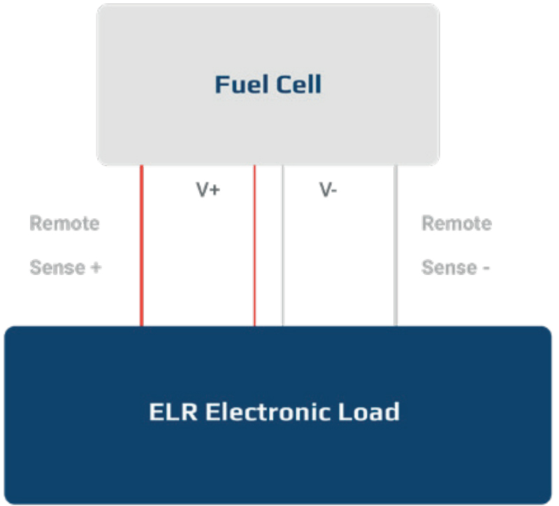
Figure 3 shows an ideal voltage for illustration, but cable inductance, L·di/dt, creates ringing on the edges of the voltage pulse when the current transitions. This can make obtaining an accurate reading of the voltage peak difficult. Keeping test cables between the load and the fuel cell-under-test as short as possible can reduce the ringing effect. Figure 4 shows the test setup for the current interrupt test.The second disadvantage of this method is that it over estimates the resistance of the fuel cell by 10 to 20%.
Click image to enlarge
Figure 3. An ideal fuel cell response to a load current interrupt.The actual output would have oscillation(ringing) on the rising edge and falling edge of the voltage pulse due to the inductance of the cabling.The transition is an AC effect so the cables act like an R-L-C transmission line during the transition of the load
Click image to enlarge
Figure 4. Test setup for measuring fuel cell resistance with the current interrupt method
A more accurate measurement method of fuel cell resistance is the AC perturbation method. This method creates a small AC current signal on a DC load current which results in a minimal disturbance to the cell. The AC signal is a sinusoidal AC current with a frequency that can be any value between1Hz to10kHz.
The challenge with the AC perturbation method is the modulation of the DC load current with a small sinusoidal waveform. For conventional electronic loads, the test setup requires a waveform generator which is a low power instrument. A connection scheme is required to safely interface the waveform generator to the electronic load that must absorb the high power of a fuel cell. The ELR electronic loads have the unique advantage of a built-in waveform generator which can modulate a DC load. This significantly simplifies the test setup for an AC perturbation measurement on the fuel cell.
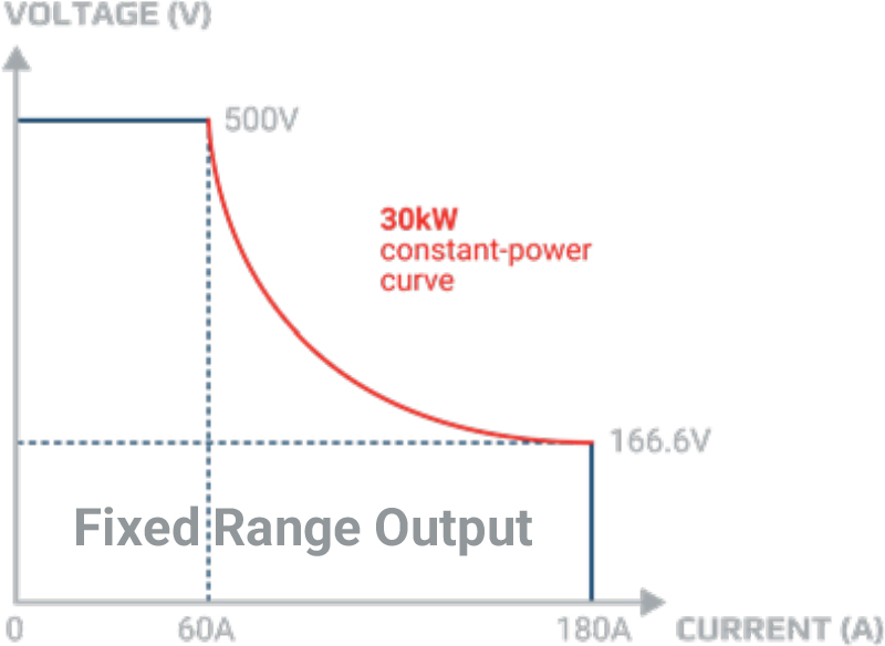
Testing a fuel cell stack which can output as much as MW levels of power requires high power instrumentation for testing. Models of ELR loads can sink up to 30kW and operate with voltages up to a maximum of 2000 V and current of 1000A.The loads have this capacity due to their autoranging input shown in Figure 5. Autoranging enables the load to absorb full power across a larger operating range than a fixed range load and avoids having to use a higher power load to sink either a higher voltage or a higher current. Autoranging also provides flexibility in testing more types of fuel cells due to the load’s wider voltage and current operating ranges.
For the large fuel cell stacks used for back-up power generation, up to 64 ELR loads can be paralleled to sink up to 64 kA. ELR load assemblies can test any fuel cell stack.
Click image to enlarge
Figure 5. Autoranging input compared with a fixed range load.Note how much higher voltage input and how much more power handling at more current settings an autoranging load offers
The most important step in testing fuel cells is to ensuretheir safety and stability. For automotive applications, a fuel cell stack must have a 5,000 hour operating lifetime. Back-up power systems must have a 10,000 hour operating life. Feasible testing requires accelerated stress testing in which a fuel cell stack is subjected to cycles of step load changes or load current ramps for over 100 hours.
The load current change should result in the fuel cell voltage changing by about 50%. The period of the square wave step change and the ramp cycle should be around 50s.
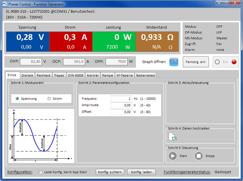
Using the built-in waveform generator, the ELR load Power Control software, shown in Figure 6, can set up a ramp test with a ramp having a 50s period.
Click image to enlarge
Figure 6. Power Control software screenshot showing the creation of a load current ramp from 0A to100A with a 50s period
A 100-hour test on a high-power fuel cell stack consumes a lot of energy. ELR loads can save substantial energy during an accelerated stress test. The loads have regenerative energy recovery which can sink power and return the power to the electrical grid with up to 96% efficiency. Not having to dissipate all the consumed power allows the ELR load to run cooler compared with a traditional electronic load. These loads require a lower investment in cooling infrastructure. Using an ELR load provides a return on investment with significantly reduced utility costs.
The ELR loads offer the following benefits for fuel cell testing:
While this article has focused on the ELR load as the primary test instrument, the PSB-series bidirectional power supplies can provide the same sinking capacity. Like the ELR loads, the PSB-series supplies have a built-in waveform generator, autoranging input and output, and regenerative energy recovery. The PSB supplies can also simulate a fuel cell stack if testing the fuel cell load as well as the fuel cell is needed. Whichever instrument is selected, both provide simplified and efficient testing of fuel cells.