Powerful New Tools Provide Better DC-DC Converters and Faster Time to Market
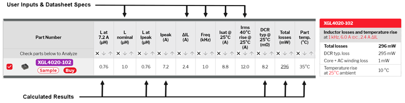
Figure 1: Inductor Performance Analysis
Design engineersuse analysis tools long before going to the bench to assemble any hardware. Experienced designers know that the best tools provide more efficient designs in the shortest possible time, and the way to be the first to market with the best converter often comes down to simply “get it right the first time”. New patent-pending upgrades to Coilcraft MAGPro power inductor tools go beyond just better inductor selection, most importantly by offering insight into possible converter design choices that only become clear when presented with a better picture of true inductor performance.
The key to finding the optimal inductor for a converter relies on understanding that inductors impact the way current flows. Simply put, it can be misleading to judge inductor/converter performance by simply comparing the performance of inductors with “x” current. This traditional way of comparing and searching for inductors can be a good approximation, but is most accurate only when inductors have the same inductance value. After all, di/dt = V/L, so to be an accurate comparison L must be equal for all inductors to be considered. That’s not as simple as it sounds. Inductors may have slightly different nominal inductance even if their part numbers make them seem the same. And more importantly, inductors can have different saturation curves so the L at any given current may be different for different inductors which is very difficult to compare from traditional datasheets. In many ways, designers traditionally had to assume that similarly rated inductors operated in similar ways. This could lead to good choices in many cases, but could also often lead to poor choices in other cases, significantly impacting converter performance. The following will discuss how the MAGPro DC-DC Optimizer innovatively addresses this challenge, and how newly released features provide even more flexibility for the designer to get a deeper look at predicting real inductor and converter performance before committing to expensive and time-consuming prototypes.
Background
Coilcraft tools have a long history of providing power inductor performance information based on application conditions. An early innovation was the Power Inductor Finder & Analysis tool that provides the opportunity to view inductor efficiency at user-specified frequency, dc load current, and ac ripple current. For example, (Fig. 1) using the innovative Compare Losses tool, the user simply selected part number XGL4020-102 (1µH), selected 1 kHz, 6 Adc, and 2.4 A ripple current to receive a raft of useful, application-specific information including a breakdown of dc vs ac inductor loss.
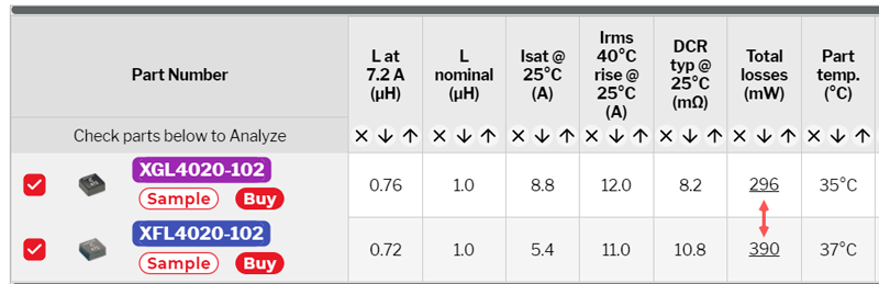
In addition to analyzing inductor loss, the tool allows easy comparison between part numbers, here easily showing a 30% efficiency difference between two similar-sized inductors (Fig. 2).
Click image to enlarge
Figure 2: Comparing Two 1uH Inductors
This tool has been used thousands of times over many years, successfully guiding users to optimal inductor selection, yet an experienced user may have noticed a significant limitation. The inputs are frequency and current, which makes for a valid comparison only between parts with the same inductance.
That’s perfectly fine but it assumesll other converter operation and components have already been defined, including the inductor specifications. This means the inductor selection process can only help optimize converter performance by finding the inductor that best matches the determined conditions, but it overlooks further optimization that other converter design choices might offer.
DC-DC Optimizer Solves the Problem
The MAGPro DC-DC Optimizer sets a new standard for power inductor selection and move [SH1] s from simply comparing inductor performance to comparing converter performance. Significantly, the user inputs are no longer merely inductor parameters like inductance and current ratings, but rather this tool starts with circuit parameters Vin, Vout, Iout, etc. This allows the tool to calculate possible converter solutions from a database of thousands of inductors without forcing the user to make artificial guesses based on old rules-of-thumb like “ripple current must be 30% of load current”.
Figure 3 shows the suggested inductor solutions for a 12 V to 5 V/5 A 800 kHz buck converter if the user specifies approximately 30% ripple current. The smallest inductor available for those conditions is a very high performance 3.3 µH inductor of 4 x 4 mm footprint, height of 2.5 mm and a very acceptable 31°C temperature rise (part temp 56°C). This would be a perfectly acceptable solution for many applications, but in a competitive market environment, we often need a solution better than “acceptable”.

Click image to enlarge
Figure 3: Inductor Solution Found by Pre-determining Ripple Current
By comparison, running the DC-DC Optimizer without pre-limiting the ripple current to any particular value, shows a 1 µH inductor of much smaller footprint can do the job. The losses are slightly increased and the inductor temperature is predicted to be 62°C, which is a fairly minimal tradeoff for essentially a 50% footprint area saving.

Click image to enlarge
Figure 4: Inductor Solution Found by Not Restricting Ripple Current
It can be seen that use of the 1 µH of course also changes the ripple current to 95% of dc load current. While this isn’t within the old rule-of-thumb it certainly might work fine with today’s smart controllers and might well be worth it to get a smaller solution than the competition.
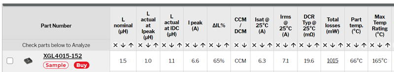
If that much ripple is not acceptable, the DC-DC Optimizer has hundreds of solutions to choose from. For example, selecting a 1.5 µH inductor reduces the inductor height from the original selection and drops the ripple current to 65% which makes it more readily adoptable in many converters. While the inductor manufacturer can’t dictate which combination is best for each user’s application, the DC-DC Optimizer provides a powerful vision of more possibilities for converter designs to be optimized and win business.
Click image to enlarge
Figure 5 Inductor Solution Selected from Range of Ripple Current Options
New Compare and Analyze Features
The MAGPro DC-DC Optimizer became the most powerful inductor selection and analysis tool by making new inductor data available and created multiple new ways to envision new converter solutions. The process of using this tool starts with circuit parameter inputs and defines the solution set of inductor/performance combinations. The Compare Losses tool has now been upgraded with a patent-pending feature to allow users to go beyond the DC-DC Optimizer and compare all inductors without returning to the circuit parameters. In short, this tool enables performance comparisons between inductors of all ratings – even different inductance values – by enabling the user to input separate conditions for each inductor to be compared.
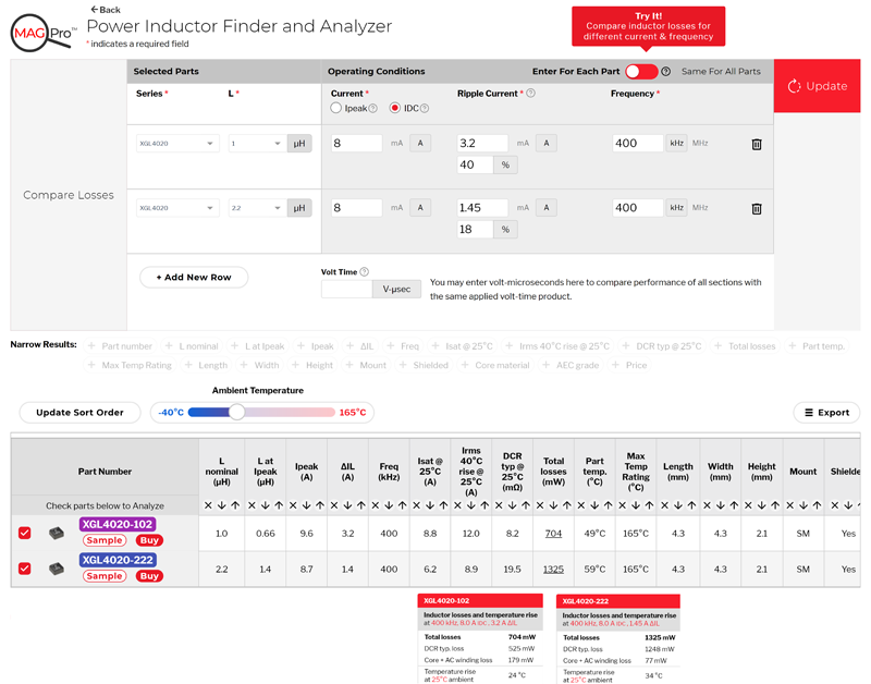
Experienced designers know that buck converter inductor ripple current is inversely proportional to inductance. One might, for example, wish to compare performance in the same circuit for two different inductances. The new Compare tool enables this in a quick and easy way. As shown in figure 6, by adjusting ripple current by the same ratio as the inductance, two different inductance parts can be compared as to how they will perform in the same converter.
Click image to enlarge
Figure 6: Comparing Inductors of Different L Value
The results show something interesting, that could almost never be predicted from comparing data sheets or even simulation tools. Which inductor will operate with lower losses and enable a higher efficiency converter? In this case the 2.2 µH shows significantly higher loss than the 1 µH part. This is easily explained by the fact that the losses are primarily dc losses for both inductors. The same load current is being forced through a lower DCR in 1 µH making it the lower loss part by far.
But consider the same example at 4 MHz instead of 400 kHz. In this case both inductors have loss dominated by ac loss, reversing the answer and making the 2.2 µH the winner. The higher inductance reduces the ripple current and that makes it a winner in an application dominated by ac loss.

Click image to enlarge
Figure 7: Comparing Inductors When Losses are Primarily AC
Conclusion
These inductor loss results are subtle and not easily predictable since data sheets really can’t easily provide enough information about ac vs dc loss across a range of applications. By using a database of measured inductor loss information and a powerful calculating engine, and providing the user input new degrees of freedom, the new MAGPro Power Inductor Finder and Analysis tool combined with the DC-DC Optimizer provides answers well beyond the intuition of even the most experienced designer. The type of data-based performance prediction gives the user the necessary tools to “get it right the first time”.