Common Driver Platform for 12V and 48V Systems
Belt-driven starter generators are an integral part of hybrid electric vehicle (HEV) and electric vehicle (EV) systems
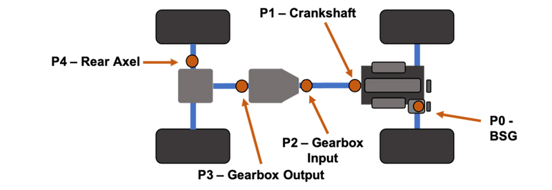
Figure 1: Starter generator and eBoost locations in an electrified vehicle
Starter generator systems play multiple roles in electrified vehicle architectures. They are responsible for starting the engine, supplying electrical boost to the engine, and generating charge voltage during deceleration or coasting, which reduces wear on mechanical braking systems while improving overall system efficiency.
No matter their architecture or where they are located, starter generator systems have proven to be an integral part of vehicle electrification. A starter generator can be used in multiple locations within a vehicle. Figure 1 shows the locations of primary starter generator systems. P0 and P1 locations are typically less than 20 kW. P0 systems are becoming very common as they are the easiest to implement, require fewer redesigns and are cost-effective. P1 locations have similar benefits while eliminating belt losses, resulting in higher performance and less wear.
Starter Generator Circuit Implementations
A starter generator system is composed of multiple electrical and mechanical components. An inverter provides electrical boost and a DC-DC converter to convert mechanical energy in the rotor to electrical energy in an energy-harvesting mode. The system is also responsible for crank position in idle stop systems as well as the high starting torque required for cold start.
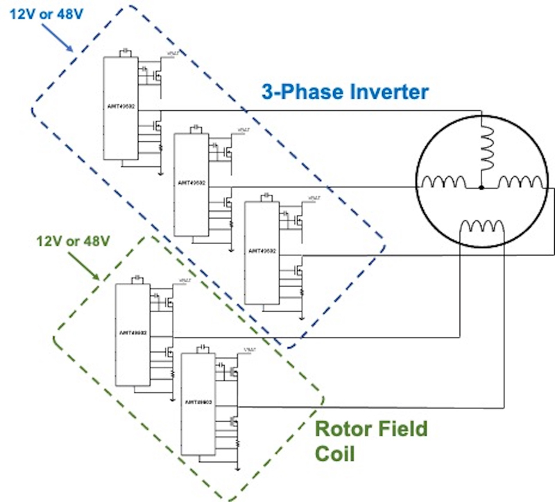
Mechanically, a starter generator comprises the stator, which is connected to a three-phase inverter, and the rotor, which generates a field by passing DC current through the rotor windings via a slip ring and brushes. Newer designs using permanent magnet machines can eliminate the need for field coils, but this approach presents other safety challenges since magnetization cannot be turned off during failure conditions. Figure 2 shows a typical circuit implementation for a five-phase machine.
Click image to enlarge
Figure 2: Example of a five-phase starter generator drive
Common Drivers For 12V and 48V Systems
Belt-driven starter generator (BSG) systems are used on both 12V and 48V power rails. A 12V BSG system is not able to provide the same power advantage as a 48V starter generator. Typically, the 12V systems are limited to < 10 kW while 48V systems can generate up to 25 kW or more. As power increases, so do the demands on the gate drivers. For P0/P1 locations, it is advantageous to use a common architecture for both 12V and 48V batteries without any additional components or redesign required. Using a common architecture reduces design time and bill-of-material (BOM) cost and enables a single platform for bolt-on BSG systems in both 12V and 48V systems.
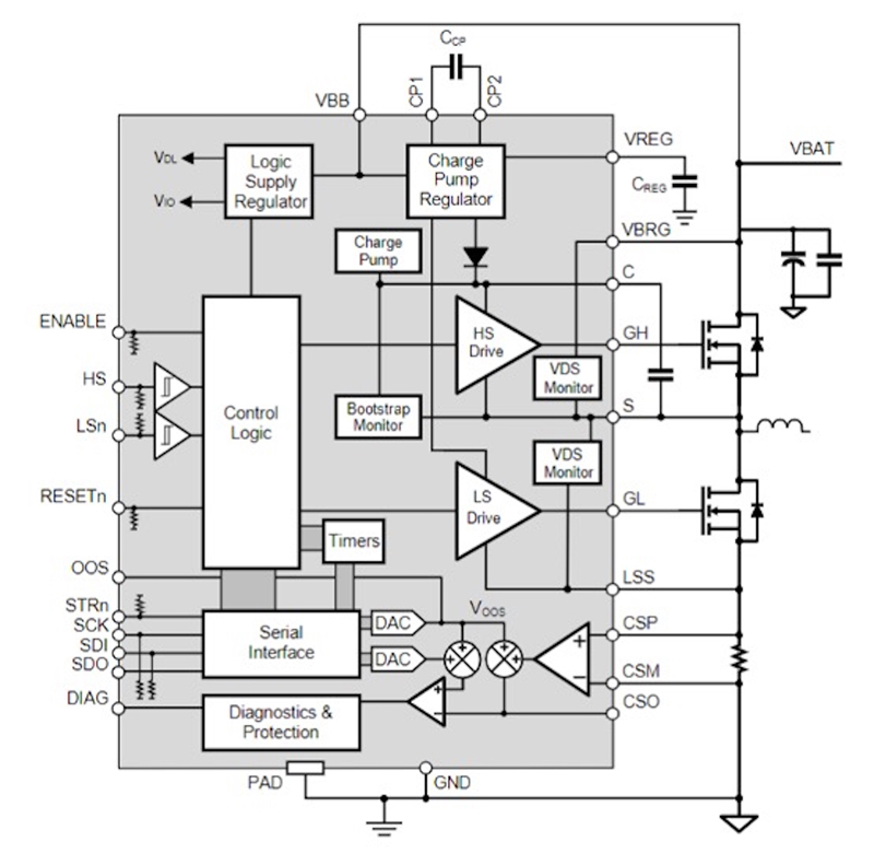
For example, the AMT49502 half-bridge gate driver from Allegro MicroSystems can operate from 5.5 V to 80 V, making it a versatile platform for BSG applications that run on a 12V rail or a 48V rail. The device’s charge pump regulator provides the gate drive for two N-channel MOSFETs. Figure 3 shows a functional block diagram for a half-bridge design. Requiring only a single supply, all internal logic is created by an on-chip logic supply regulator powered by a charge pump regulator. The regulator is responsible for providing regulated 11 V to the floating boot strap capacitor, which ensures the high-side MOSFET has 11 V on the gate with a battery voltage of 5.5 V. The charge pump regulator also supplies the internal logic, which reduces the chip’s overall power dissipation. Minimizing power consumption is key to operating at 48V without requiring buck regulation. In addition, a small integrated charge pump is responsible for holding the high-side switch on at 100 percent duty cycle.
An integrated, high-performance current sense amplifier measures current through a low-side current shunt, enabling each phase current to be fed back to a microprocessor. Independent current sensing on each of the three phases in the inverter enables full field-oriented control (FOC) with redundancy. Each MOSFET can be independently controlled using the logic inputs along with a secondary ENABLE input, which provides an independent path to disable the bridge or to activate sleep mode. A serial peripheral interface (SPI) port is available to read out diagnostics and set functional parameters.
Click image to enlarge
Figure 3: Functional block diagram for the AMT49502 gate driver
Designed for Demanding Environments
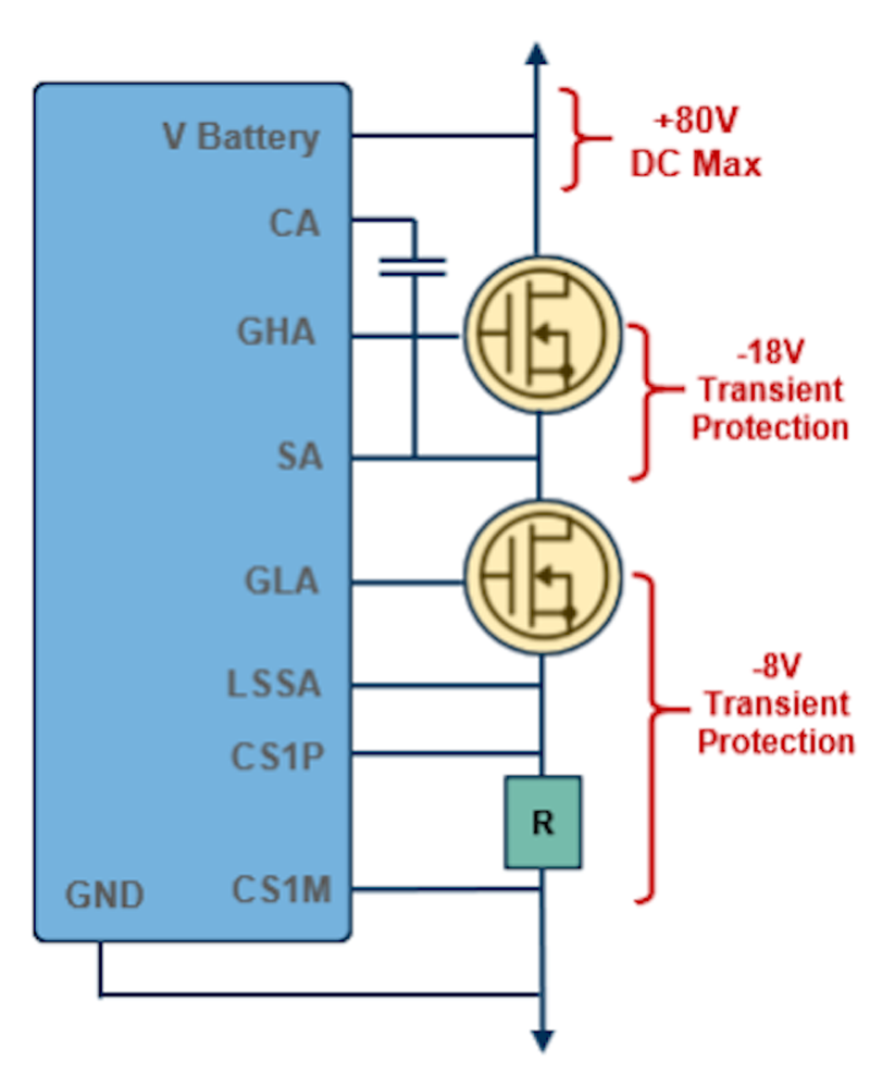
Starter generator systems can produce high voltages on the inverter bridge. When in generator mode, the inverter’s purpose is to convert three-phase currents into DC voltage and current that can be applied to the 12V or 48V battery system as charge. Ultimately, the voltage created by the motor is based on rotational speed. It is important for the inverter bridge to survive voltage transients that exist during high-speed rotation and during the transitions from drive and generator modes. The gate drivers must be robust enough to handle the high currents and voltage transients that exist in the system. By designing the gate drivers to survive these transients, the developer saves valuable design time and minimizes the additional cost of adding high-voltage clamps to protect the system. When a high-side MOSFET turns off in generator mode, the voltage transients on the bridge can produce negative voltages of more than 5 V on the low-side driver and more than 10 V on the phase node. The AMT49502 gate driver can survive –8 V on the low-side gate and –18 V on the high-side drive with respect to the phase node, as shown in Figure 4. A combination of robust transient performance and an intelligent control algorithm can ensure that even high-power systems do not damage the inverter.
Click image to enlarge
Figure 4: Typical transient performance for a 48V architecture
EV components must be robust enough to handle both negative voltage transients and pass manufacturers’ electromagnetic emission requirements. Starter generator inverters need to switch quickly to maintain efficiency while providing the best emissions reduction possible. They also must limit the magnitude of electromagnetic emissions to meet strict OEM requirements.
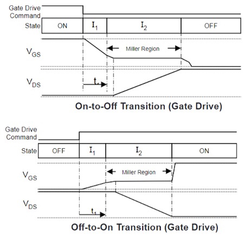
To satisfy the tradeoff between high efficiency and low electromagnetic emissions, the AMT49502 driver features a piecewise programmable current gate drive topology that allows controlled turn-on and turn-off of all the MOSFETs in the system. MOSFET off-to-on and on-to-off transitions are controlled as detailed in Figure 5. All parameters are programmed through a SPI port. When a gate drive is commanded to turn on, a current, I1, is sourced on the high-side or low-side gate terminal for a duration, t1.These parameters typically should be set to quickly charge the MOSFET input capacitance to the start of the Miller region as drain-source voltage does not change during this period. Thereafter, the current sourced on GH or GL is set to a value of I2 and remains at this value while the MOSFET transitions through the Miller region and reaches the fully on state.
MOSFET on-to-off transitions are controlled as shown in Figure 5. When a gate drive is commanded to turn off, a current, I1, is sunk by the high-side or low-side gate terminal for a duration, t1. These parameters should typically be set to quickly discharge the MOSFET input capacitance to the start of the Miller region as drain-source voltage does not change during this period. Thereafter, the current sunk by the high-side or low-side gate terminal is set to a value of I2 and remains at this value while the MOSFET transitions through the Miller region and reaches the fully off state.
Click image to enlarge
Figure 5: Depiction of a programmable piecewise gate drive
Full control of MOSFET switching increases efficiency and reduces EMI. Reducing deadtime and the time required for the MOSFET to reach its Vt enhances inverter performance by minimizing the time for high-side and low-side MOSFET switching and improves the fidelity of the sinusoidal current. Programmable current during the Miller region controls the MOSFET slew, which limits emissions while maintaining efficient switching times.
Allegro’s A49100 three-phase gate driver with ASIL D certification is available for purely 48V systems. Using a three-phase driver onboard shrinks package content, enabling even smaller system designs. The A49100 offers additional diagnostics and the ability to verify each diagnostic with built-in test circuitry. For single-driver designs, this additional diagnostic and verification function provides a level of functional safety that can notify the engine control unit (ECU) of a variety of failures.
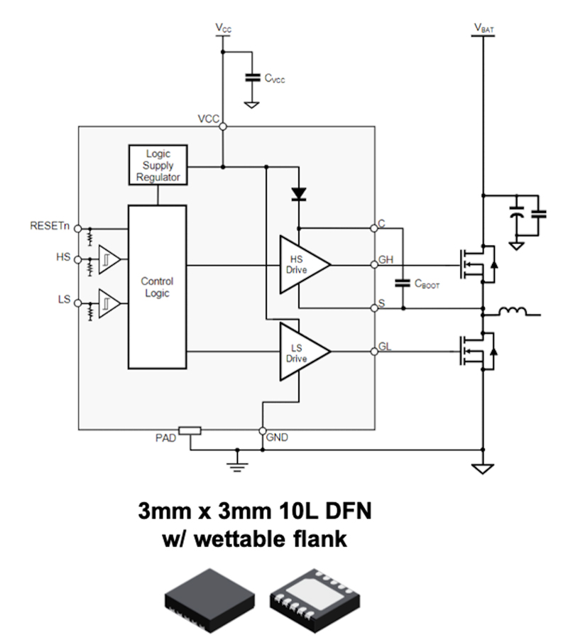
Some 48V designs may benefit from ultra-small gate drivers. For example, the 10 to 100 V A89500 half-bridge gate driver in a 3 mm × 3 mm DFN package is so small, it can reduce overall printed circuit board (PCB) space. The device can be used in a field coil drive, as well as the inverter with proper safety analysis. The driver is suppled directly with an 8 to 13 V gate supply, and the field-effect transistor (FET) bridge connects directly to a 48V battery. See block Figure 6 for details.
Click image to enlarge
Figure 6: A89500 gate driver functional block diagram and package
Designed for Safety
Starter generator failures can result in overcharge of the Lithium-ion battery pack, which can be dangerous should cells short. Therefore, starter generator circuits must comply with the ISO 26262 standard, typically requiring a “B” level certification. For example, a failure in the inverter bridge while the generator is still spinning at high speed can cause overcharge condition. In a five-phase system, one solution is to effectively remove the magnetic field on the rotor by disabling the field coil driver. In this implementation, the design is paramount to developing a failsafe system. The gate drivers in this system can make the requirement easier to achieve if they are designed for safety. The AMT49502, for example, was designed on an ISO 26262-certified development process, and the device is certified as ASIL B compliant.
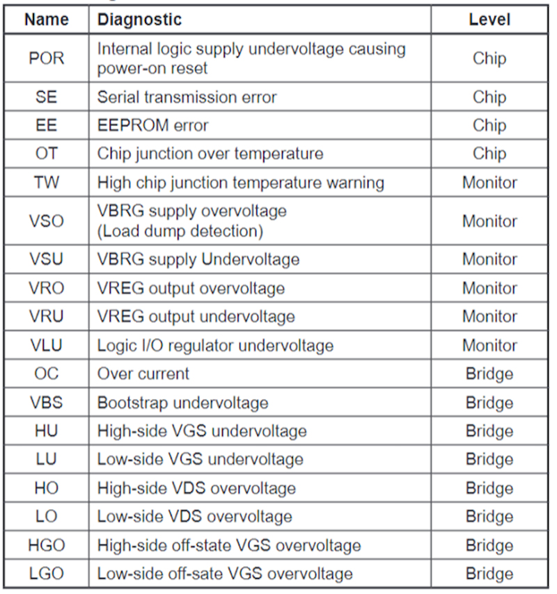
Featuring a suite of advanced diagnostics, each half-bridge driver contains nearly twenty diagnostic functions including load dump detection, MOSFET short-circuit protection, gate drive undervoltage, bridge supply overvoltage, temperature warning, and other conditions. IC diagnostics provide the system controller with necessary information to monitor operation and make decisions on actions taken by the system to ensure failsafe operation. Figure 7 shows the diagnostic features supported by the AMT49502 gate driver.
Click image to enlarge
Figure 7: Diagnostic functions on the AMT89502 half-bridge gate driver
Conclusion
BSG systems are becoming more common in HEV motor control designs due to their easy implementation, similar footprint to existing alternator systems and the elimination of major modifications to the powertrain (in P2 – P4 locations). As starter generator systems continue to evolve, further integration may impact the role of BSGs over time. Going forward, 48V systems will likely dominate in P3 – P4 locations.
As the electrical revolution continues to transform the automotive industry, electrification will continue to gain market share, and 12V solutions will give way to higher battery voltages. Using a common platform for both 12V and 48V systems will simplify and ease the transition to 48V solutions. Starter generator systems will also benefit from industry-leading safety diagnostics, redundancy offered by independent bridge control and current sensing, and robust transient performance.