Fast & efficient power management solutions maximize reliability
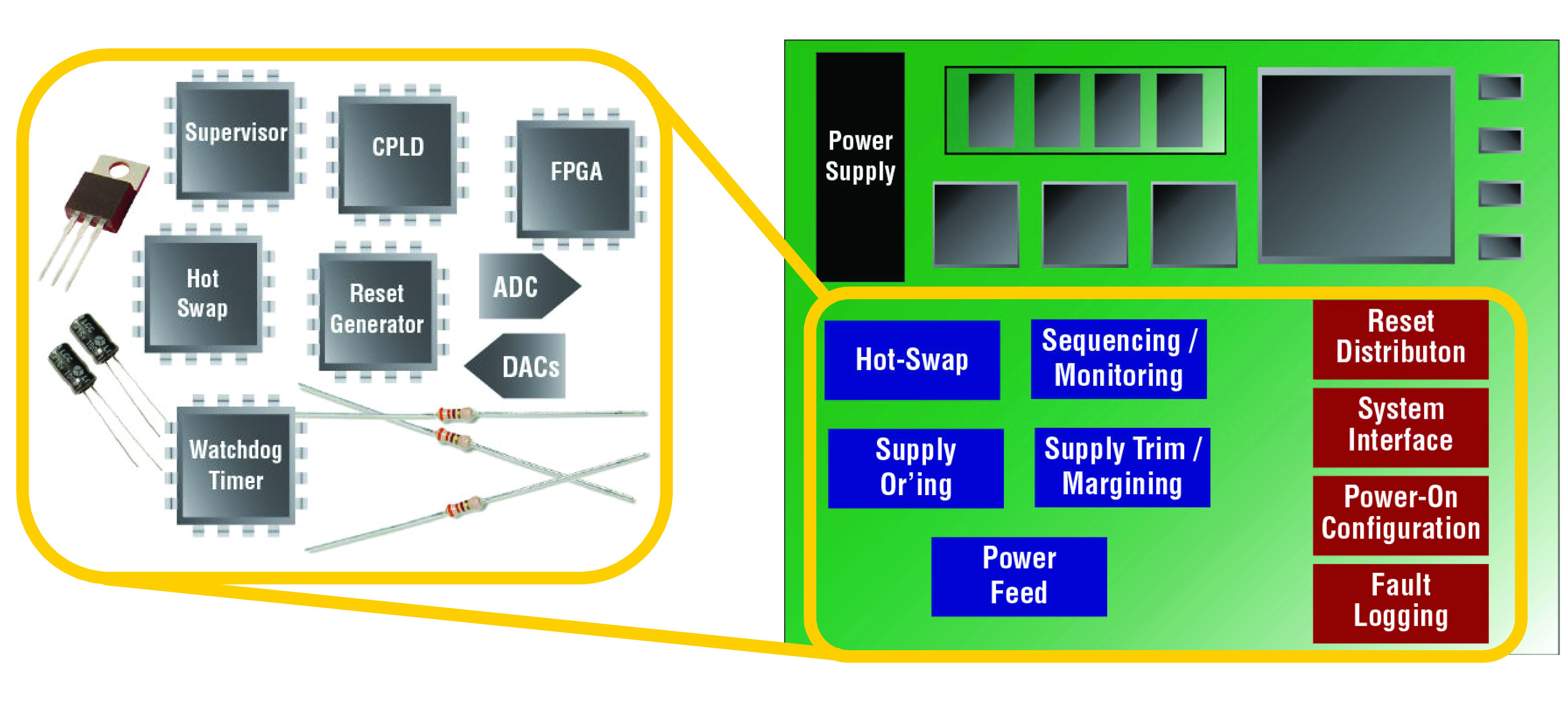
The explosion in data traffic and the introduction of "Smart Phones" such as the Apple iPhone are fuelling the need for the rapid expansion of communications networks, not only at the Edge but also in the backhaul networks. Communication equipment manufacturers and suppliers must meet stringent contractual demands by the network operators for such things as Quality of Service (QOS) and Class of Service (COS) requirements. Failure to do so may lead to penalty clauses being invoked, which may mean heavy fines for the supplier. The equipment uptime requirement of 99.999%, also known as the five nines, is typically quoted for the reliability of the service. Complex designs Communications design engineers are increasingly using complex devices such as ASICs, ASSPs, communications processors and FPGAs to provide the right solutions in the network and switching fabric. These devices will have very different power requirements from each other, not only in voltages but in the sequencing of those voltages. Additionally, in the case of rack mounted equipment, the actual PCB can be of a substantial physical size and may contain all of the above devices. It is therefore essential that, in order to ensure the correct operation of the design, very careful thought must be given to the provisioning of power on the board. These complex devices require multiple board-mounted power supplies that need to be turned on and off in a specific sequence, monitored for faults and trimmed for voltage accuracy. In addition, the input power to the board often requires redundant power management and, in the case of plug-in boards, hot-swap functionality. All the functions that control various power rails comprise the need for power management. After all supplies are turned on, the system requires digital support functions such as reset distribution, start-up configuration control for FPGAs and ASSPs, watchdog timers and a system bus interface for a microcontroller. These digital support functions require digital management. Power and digital management together are often referred to as board or platform management. Traditional approach The traditional approach to power management has been to use many single function ICs and discrete components in order to provide the solution; however, this approach has a number of disadvantages. The large number of devices results in a high bill of materials as well as increased board size. This has a direct effect on board reliability and may also mean that all the signals are not monitored accurately. If the board requires a re-spin of the design there could be a corresponding change in the power requirements. This approach is shown in Figure 1. The blue coloured blocks show the analogue functions and the red show the digital functions for power monitoring. The black or grey components represent the payload, or primary, function being implemented.
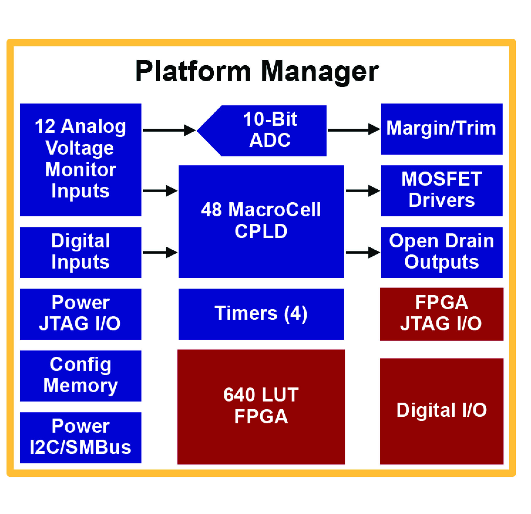
The programmable solution In order to overcome the disadvantages to the traditional approach, Lattice has now introduced its third generation family of mixed signal devices, namely the Platform Manager family. These programmable devices significantly simplify board management design. The Lattice Platform Manager integrates board power management (hot-swap, sequencing, monitoring, reset generation, trimming and margining) and digital board management functions (reset tree, non-volatile error logging, glue logic, board digital signal monitoring and control, system bus interface, etc.) into a single chip. The block diagram is shown in Figure 2. The Platform Manager can monitor up to twelve power supply test points through independent analog input channels. These input channels can be monitored through differential inputs in order to support ground sensing. Each of the analog input channels is monitored through two independently programmable comparators to support both high/low and in-bounds/out-of-bounds (window-compare) monitor functions. Up to six general purpose 5V tolerant digital inputs are provided for miscellaneous functions. The device also contains a 48-macrocell CPLD and a 640 LUT FPGA. The status of all the comparators on the analog input channels as well as the general purpose digital inputs are fed to the inputs of the CPLD array, whose outputs then control all the digital outputs (open-drain as well as HVOUT). The FPGA section of the Platform Manger is optimized to meet the digital board management requirements and uses distributed memories for flexible and efficient logic implementation. The instant-on capability enables the device to integrate control functions that are required as soon as power is applied to the board. Instant-on In complex systems it is essential that power be applied to the individual devices according to their precise specifications and in the correct order. If one relied on a microprocessor for this function the system would have to wait until the processor had gone through its boot sequence before the rest of the system could be powered. This could lead to a number of problems such as the delay in start up, and signals being applied to other devices in an uncontrolled manner. Platform Manager over comes this potential problem by using its non-volatile memory for the configuration. Backplane management and hot swap In communications systems where rack and shelf mounted boards are common, plug in boards communicate with a shelf manager to provide information about the board configuration. The shelf manager checks to determine that the correct card has been inserted. Only after receiving the turn on command from the shelf manager is the payload turned on. Reset tree The Platform manager also provides an efficient mechanism for reset distribution. In many cases the individual devices on a board must be reset in a controlled manner. Various resets such as PLL Locked, Memory Controller ready, FPGA-done etc may need to be synchronised to the system clock. In other designs Reset sequencing is needed to minimise peak current consumption for a reliable start up
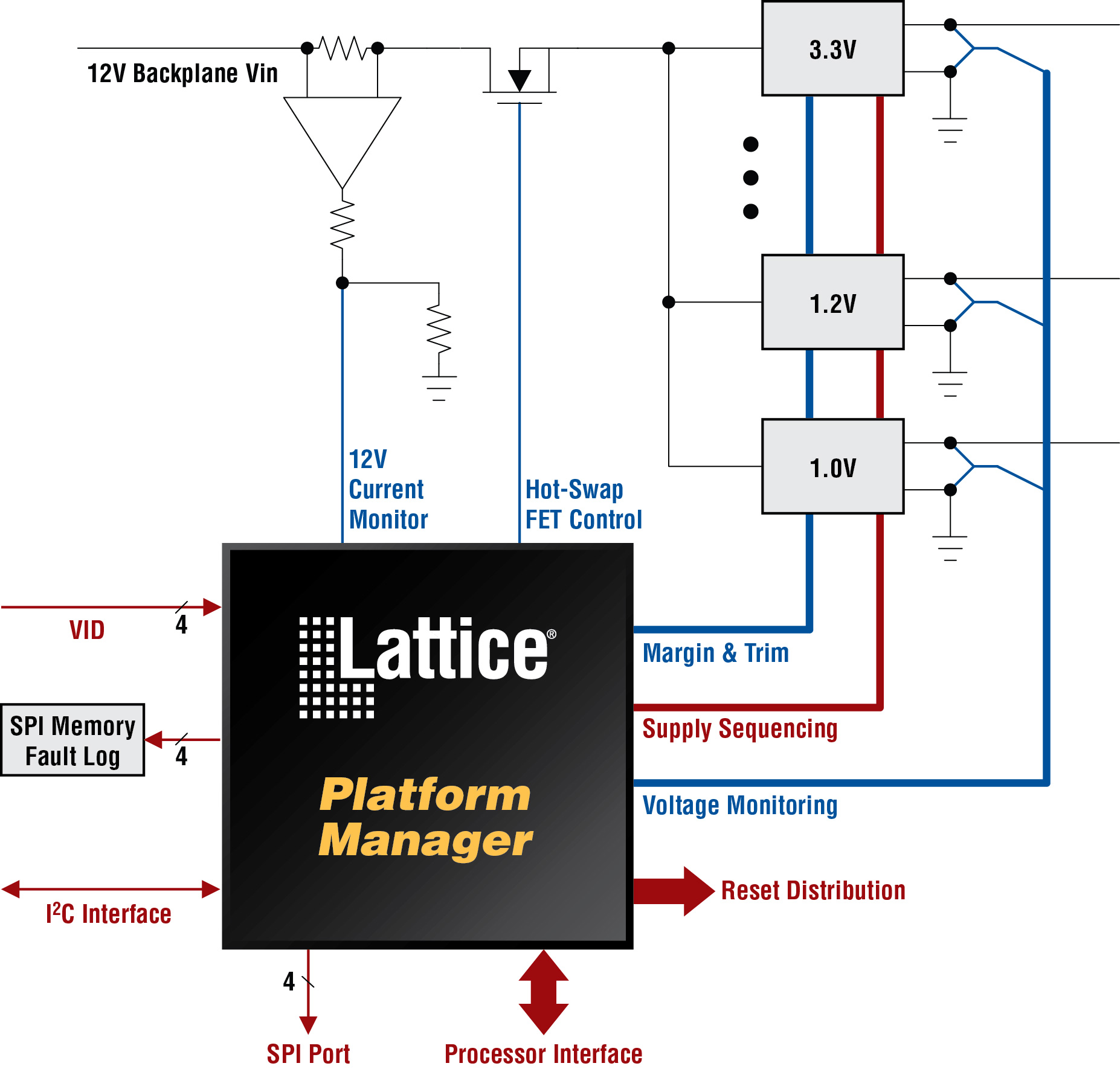
Typical application A typical application of Platform Manager is shown in Figure 3. In this example, the Platform Manager is able to detect faults across 12 supplies. These are represented by the black dots. It can trim up to 8 supplies; this is a key function and will be described more fully later. The device is also able to capture and log information to the non-volatile SPI memory. The voltage monitoring function is shown connected to the differential outputs of the various power outputs. VID control Certain ASIC and CPU devices that have been fabricated using 45nm or below sometimes require different core voltages in order to meet their datasheet performance. The required core voltage is encoded and can be read by the board management logic as its Voltage ID, or VID. In order to meet these sometimes stringent demands the the use of precise and expensive power supplies is typically required. By using the VID information, the Power Manager can use the Margin and Trim circuits to precisely control the various power voltages and consequently a less costly DC to DC converter can be utilized. Design and evaluation In order to facilitate and accelerate the design cycle, Lattice provides a number of tools and options. The family is supported by PAC-Designer 6.0 software and the starter version of ispLever design software tools. These are free tools that may be downloaded from the Lattice website. Also available are four free reference designs and three free IP cores that implement common functions, such as fault logging into Non-volatile Memory, Closed loop Margining and interface to I2C or SPI bus masters. Additionally, a low cost Platform Manager development kit containing an evaluation board complete with demonstration code and documentation is available for purchase. This board allows users to see known good hardware in about five minutes and to recompile the provided source code in order to get to a known good starting point in thirty minutes. This is an invaluable way for engineers to familiarize themselves with the capabilities of the device before beginning their own design in earnest. Summary The Platform Manager is a flexible, programmable device that can be customized to solve many of the problems engineers face in providing the power and control functions required in modern complex designs. By integrating many of these functions into a single device, the Platform Manager can reduce the overall system cost and, because of the reduced component count, can significantly improve system reliability. www.latticesemi.com