Complex 800V Battery Pack Testing in a Single PXI Chassis

Stephen Jenkins from Pickering Interfaces tells PSD how the company’s new battery tester helps test large battery packs
Battery management systems (BMS) are important parts of almost every battery powered application. They are used to control the charging and discharging cycles and ensure each cell is safe and performs as expected. It is not always possible to test the BMS with real batteries, mainly due to the safety issues of using high voltage battery packs in the lab. In their place, battery testers are used to emulate the behavior of battery cells and packs at different stages of charge, battery health and loads.
Battery testers normally operate in two quadrants, sourcing and sinking currents with a positive voltage to simulate both charging and discharging, along with replicating any fault conditions necessary to the testing. Power supply units are sometimes used as battery testers, but they don’t often have the flexibility, or levels of control required for today’s complex testing. Battery simulators are an alternative that allow both sourcing and sinking of positive voltages and positive and negative currents, providing the ability to test both charging and discharging. Adding a source measurement unit makes battery simulators even more versatile. However, battery simulators usually tend to be quite expensive. Sitting between these two types of battery tester is Pickering Interfaces’ battery simulator card, which comes in the PXI form factor and allows comprehensive testing at a more reasonable price.
Explaining the need for BMS testing, Stephen Jenkins, Simulation Product Manager at Pickering Interfaces said, “Our customers are using battery simulators in two main areas, in the lab, verifying and developing battery management systems, and also in cell balancing applications. They want to test the behavior of battery powered electronics over varying states of charge. For example, mimicking voltage behavior at different temperatures, battery ages, and internal resistances for environmental life cycle testing. The PXI form factor allows the simulator cards to be used with fault insertion units to mimic a cell going open circuit or short circuit, and thermocouple cards to simulate the temperature of the battery pack, allowing testing of how the battery management system will respond at different temperatures.”
Initially, the company developed a single PXI slot, 4-channel battery simulator, with each channel capable of supplying up to 7V and 300mA. The channels is fully isolated from ground and from each other, allowing a series connection to simulate batteries in a stacked architecture. Every channel features independent power and sense connections, allowing the simulator to sense a remote load and correct for wiring losses. The battery simulator responds to dynamic loads and can independently read the voltage at the load and current for each channel. However, the battery market has evolved and those capabilities are no longer sufficient for the demanding requirements of today’s designs.
Jenkins explains, “In a 400V system, with 15 cells in each module, and six modules connected together, each channel could simulate one cell. Simulating the 90 4.2V cells requires a full 21 slot PXI chassis, which is just about manageable. That solution has, so far, worked well for customers. However, now we are seeing bigger battery packs, with 800V systems, and some of our customers are even planning to move to 1.2KV in the future. If you are doing that with 15 cells per module, you end up with 12 modules, and then you’d require two 21” racks completely full of 300 mA cards to do the cell balancing. Doubling up on chassis is not a great idea. It increases the budget, and the additional cable lines add complexity and introduce the possibility of crosstalk. Additionally, having a set-up like that in the lab means you're potentially subjecting staff to hazardous voltages in testing. For those reasons, and from customer requests, we have developed a new 5A battery simulator.”
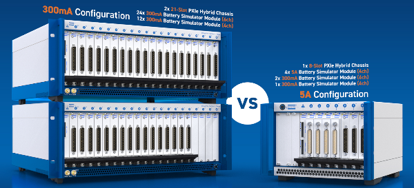
The new single-slot form factor models 41-754 (PXI) and 43-754 (PXIe) are 2- or 4-channel battery simulators, capable of supplying up to 8V and 5A per channel. Again, the channels are fully isolated from ground (100V) and from each other (750V) for stacking.
Jenkins continues, “There is an exponential growth of complexity and cost when going from 400V to 800V testing. With 5A per channel in the new simulator, the cell management controllers can be connected in parallel. If, however, we use a 5A simulator for each channel, it is possible to set up the 16 cells in parallel, while still providing the 300mA balancing current to test the BMS in the lab. That brings us back to one slot per module and a single chassis.”
The PXI form factor allows the battery tester to be easily integrated into modular test systems. Additional modules can be easily added if higher voltages are needed. The modular approach also supports integration with other PXI/PXIe instruments, such as fault insertion units (FIUs) or thermocouple simulators, for advanced failure and thermal response testing.
In software development and cell balancing applications, the 5A battery simulator enables low-compliance voltage open-loop setups for engineers’ desktops, which can be scaled up to closed-loop applications in Real-Time systems. This hardware-in-the-loop (HIL) testing enables the simulation of battery models, alongside embedded control systems, allowing for real-time testing of algorithms such as state-of-charge, state-of-health, and cell degradation.