Considerations in Choosing a Medical AC-DC Power Supply

Common questions answered for selecting power supplies for medical applications
Choosing a power supply for medical equipment applications can be challenging, to ensure that the correct qualified power supply is chosen. The following article is intended to dispel some of the uncertainty and provide a brief overview of some of the terminology and some of the areas to be considered in the field of medical power supplies.
What is a Medical-Rated AC-DC Power Supply...??
One that has been evaluated and certified to the latest medical standard e.g., IEC 60601-1.
The medical standard has specific requirements for “Means of Protection (MOP), and particularly of the patient.
These are:
· MOOP(Operator)
· MOPP(Patient)
|
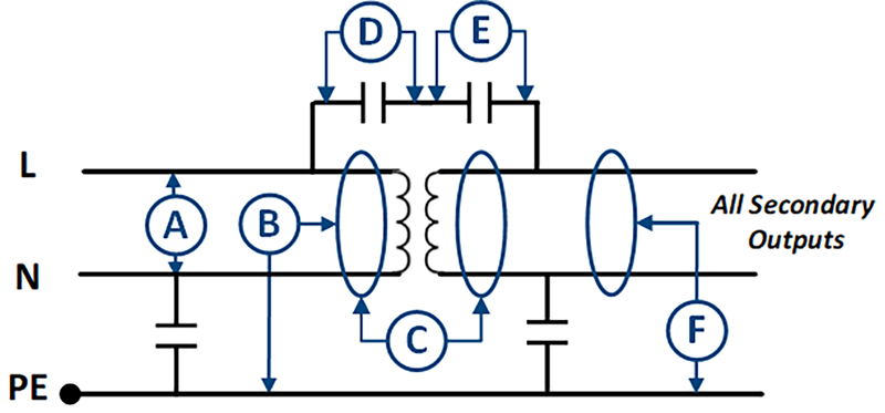
· Area “A” = 1 x MOOP |
· Area “D” = 1 x MOPP |
|
· Area “B” = 1 x MOPP |
· Area “E” = 1 x MOPP |
|
· Area “C” = 2 X MOPP |
· Area “F” = 1 x MOPP |
This can be important in the end (system) application. If the power supply output is connected to the patient without 1MOPP isolation from the power supply, there is a potential system-level non-compliance.
The End User can be confident that the MOP, built into any medical-approved Murata Power Solutions (MPS) power supply, has been assessed by a third-party accredited safety agency.
This alleviates one of the potential quandaries for the End User.
However, there is still a requirement to determine which level of MOP is applicable to the intended deployment.
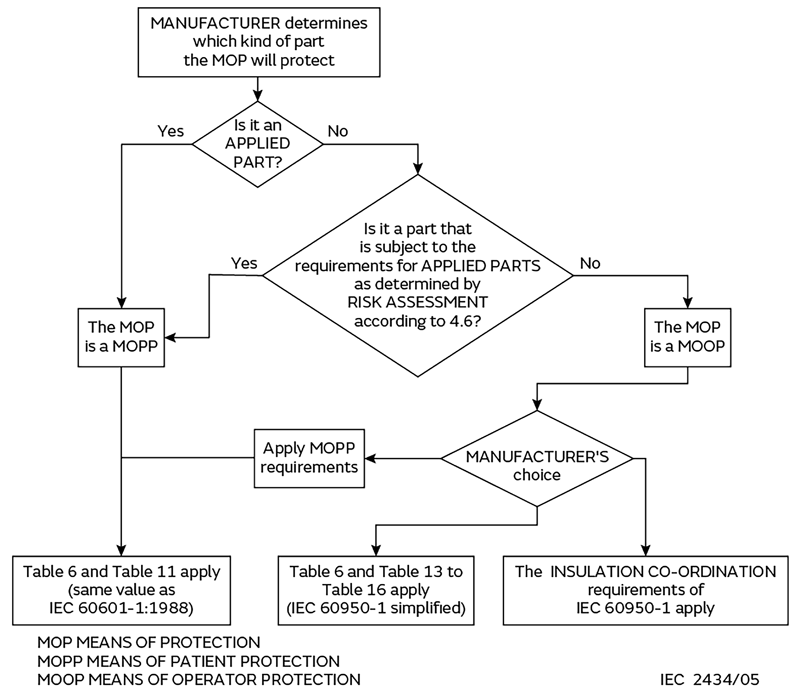
Figure 2 (extracted from IEC60601-1 Ed3) shows the decision-making process, in flowchart form, to assess and determine the type of protection (MOP) required (for any medical equipment) application:
Click image to enlarge
Figure 2: Decision-making process to assess and determine the type of protection (MOP) required
The first decision box refers to “APPLIED PART”; what is that exactly?
An Applied Part is one that can be in contact with (i.e., applied to) the patient. This is the first fundamental decision to be made by the End User, based on the following three Types of Applied Parts vs. the intended application:
· Type B (Body): This type is (or may be) in contact with the patient’s body that may be connected to earth. Therefore, the associated “risk” is excessive patient leakage current.
Examples of equipment that may be Type B rated are LED lighting, medical lasers, MRI/CT body scanners, hospital beds, and phototherapy equipment.
· Type BF (Body Floating): This type is also in contact with the patient’s body; however, the patient is not directly connected to earth i.e., considered to be “floating” with respect to earth. Again the “risk” is excessive patient leakage current. Examples of this type of equipment are blood pressure monitors, incubators, and ultrasound equipment.
· Type CF (Cardiac Floating): This type is intended for equipment for direct cardiac (or bloodstream) application; as such, the patient leakage current allowed maximum limit is extremely low. Examples include dialysis and surgical equipment.
Note that power supplies are not medical equipment, or applied parts, and should not be directly connected to a patient.
If none of these apply, then the intended application does not (mandatorily) require an Applied Part rated power supply, although this does not necessarily mean that some form of medical certification will not be required.
Once this decision has been made then research of suitable products can be undertaken that, not only meet the operational requirements for the intended application, but as importantly, the correct level of MOP.
Leakage Currents and How They Influence the Selection of the Power Supply
Another often confusing parameter is the subject of Leakage Currents.
IEC 60601-1 Ed 3 defines three main types1 of leakage current as follows:
· Earth Leakage Current
· Enclosure (Touch) Current
· Patient Leakage Current
Leakage (unwanted) current can be AC or DC in nature (or a combination of both) from the input (AC source side) and/or the output side of the power supply.
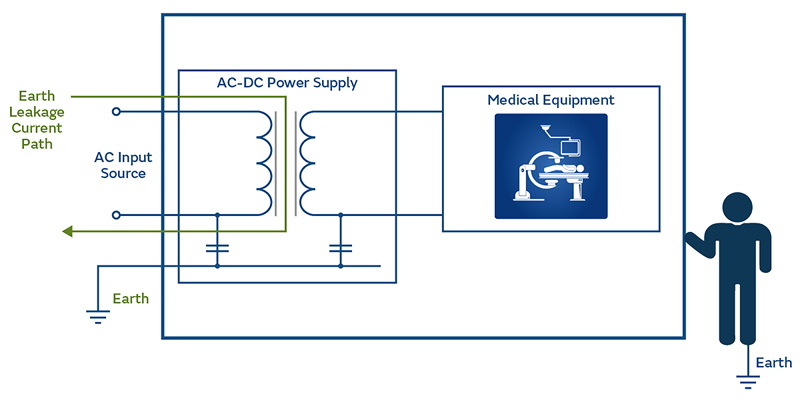
Earth Leakage Current:
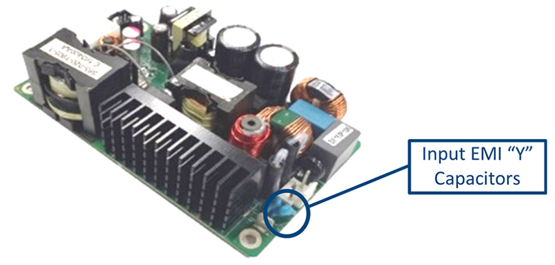
Figure 3 shows the current that flows from the AC input source (generally via capacitance within the power supply) through the earth conductor (Protective Earth).
The capacitance can be both parasitic (stray) and due to capacitance intentionally placed between the AC source connections (live and neutral) to earth (to reduce EMI Emissions).
There is no risk if the earth connection is solid as no current can flow through the patient/operator to earth (even if directly in contact with the enclosure).
Under normal conditions the allowable current is 5mA and for Single Fault Conditions (SFC) is allowed to be 10mA.
Figure 3 also shows the position of the EMI “Y”caps, on a Murata Power Solutions PQC250 open frame power supply.
Click image to enlarge
Figures 3a and 3b: Current that flows from the AC input source through the earth conductor
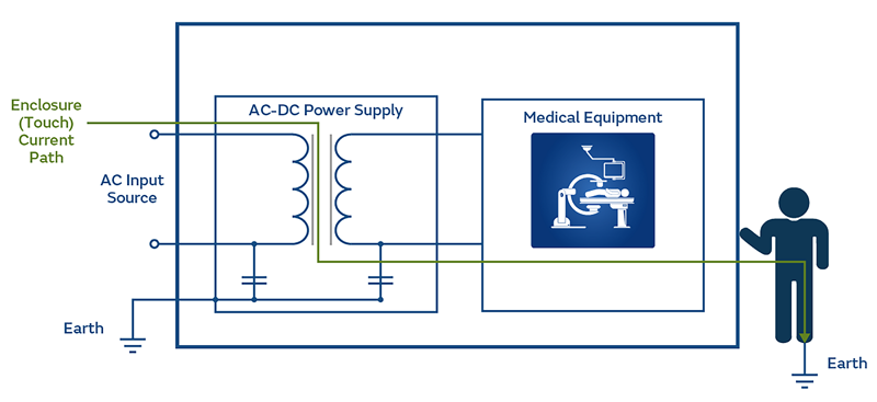
Enclosure (Touch) Leakage Current:
Figure 4 shows the current that would flow if the patient (or the operator) were connected to earth and in direct contact with the enclosure.
Under normal conditions, the allowable current is low (100µA) and for Single Fault Conditions (SFC) is allowed to be 500µA.
Click image to enlarge
Figure 4: Current that would flow if the patient (or the operator) were connected to earth
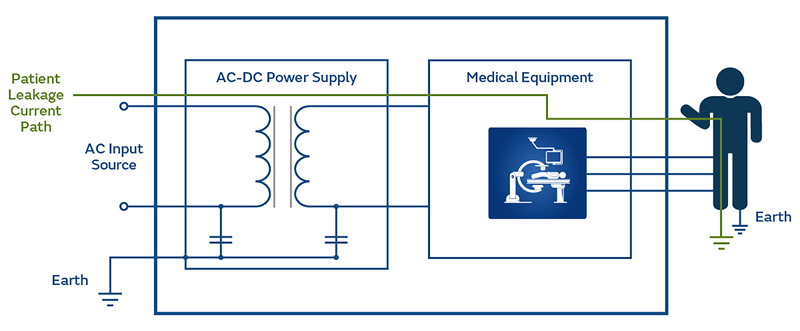
Patient Leakage Current:
Figure 5 shows the current flowing between an item of medical equipment and through the Patient to earth. This is considered Normal Conditions (NC) under The allowable current is 100µA. Under Single Fault Conditions (SFC) this allowable current is 500µA.
Click image to enlarge
Figure 5: Current flowing between an item of medical equipment and through the patient to earth
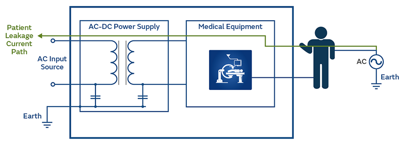
Leakage current can also flow from another source i.e., another item of medical equipment, connected to the Patient, to earth (as shown in Figure 6).
Click image to enlarge
Figure 6: Current can flow from another source (medical equipment), connected to the patient
There is a fourth leakage current mentioned in IEC 60601 Ed 3, however, this is out of the scope of this brief.
Grounding; Class I and Class II Equipment
Class I and Class II equipment is referred to, in IEC 60601-1 Ed 3 in the context of the protection against electric shock.
Class I:The equipment is intended to be provided with a Protective Earth (PE) and the insulation system between the primary and all metal, or internal metal parts, is basic only. In other words, a PE connection must be present on the metal enclosure of the equipment. Equipment intended for Class I connection to the utility are provided with three connector terminals (one of which will be designated the PE contact).
Class II: The equipment is not intended to be provided with a PE connection, therefore, the level of insulation, between the primary and all metal or internal metal parts, requires to be supplemented by double or reinforced insulation.
· Equipment intended for Class I connection to the utility are provided with a connector that will be provided with a PE contact (See Figure 7).
· Equipment intended for Class II connection to the utility are usually provided with a two-terminal connector.
- However a three-terminal connector can be provided with the ground used for EMI purposes, but this will not be considered a PE contact.
- Usually, the enclosure of the equipment is non-conductive (plastic). However, metal cases are allowed for Class II product assuming that 2xMOOP is provided from primary to PE/Ground and the End User.
Basically, it will require to be determined by the End User, which insulation Class is required based upon:
· Is the enclosure intended to be conductive (metal)
· If so, then is a PE connection available; choose a power supply with a suitable connector.
Examples of Murata Power Solutions Products for Class I implementation:
Click image to enlarge
Figure 7: PQU650M-xxP – Three pin header with integral PE
Summary
This article has provided an overview of some of the common questions that will be encountered when initially selecting a suitable power supply for a medical application. Initially reviewing Means Of Protection, for Patient and Operator, and it’s bearing on the relevance of the power supply selection, for a given type of medical equipment.
Depending on the outcome of this decision it will be necessary to determine if the medical equipment is an “Applied Part”and which of the types are required. It is important to note that the power supply cannot be an Applied Part, in and of itself, however, it can influence how the medical equipment is deployed, in this respect.
An important parameter, is leakage current, and this article has reviewed the different types, and how they also influence the choice of the power supply for the intended medical equipment deployment.
Lastly, grounding was reviewed and discussed in relation to the choice of power supply.
Murata Power Solutions can offer power supply solutions that would be suitable for many medical equipment applications. Our team of experts would be pleased to provide guidance and assistance in the selection of a recommended model for medical equipment deployment and provide technical support.