Author:
Aengus Murray and Bob Zwicker, Analog Devices
Date
07/25/2014
 PDF
PDF
Concerns over climate changes due to carbon emissions have resulted in the increasing application of power electronic inverters in both renewable energy applications and in energy efficient motor drives. Safe and reliable operation of these systems requires that the power electronic circuits connected directly to the ac power lines are isolated from the user. Systems must comply with strict safety requirements defined by International standards such as IEC61800 and IEC62109 covering applications such as motor drives and solar inverters. In some regions there is a more onerous burden because the design engineer may be personally liable in the case of an injury resulting from a failure of a safety function on a system he designed.
When compared to traditional Optocouplers isolation, high-speed magnetic isolation technologies deliver higher system performance and reduced circuit size because of the higher speed, higher levels of integration and lower power consumption. The challenge for the designer in adopting a new technology is the introduction of a new architecture, circuit, or component for isolation circuits requires significant system level evaluation. Component suppliers meet this challenge by performing component level testing and certification that guarantees a components ability to meet safety isolation and reliability requirements. Here we’ll describes system isolation architectures and explore architectural options presented by the availability of faster and more accurate isolation components.
Isolation Architectures
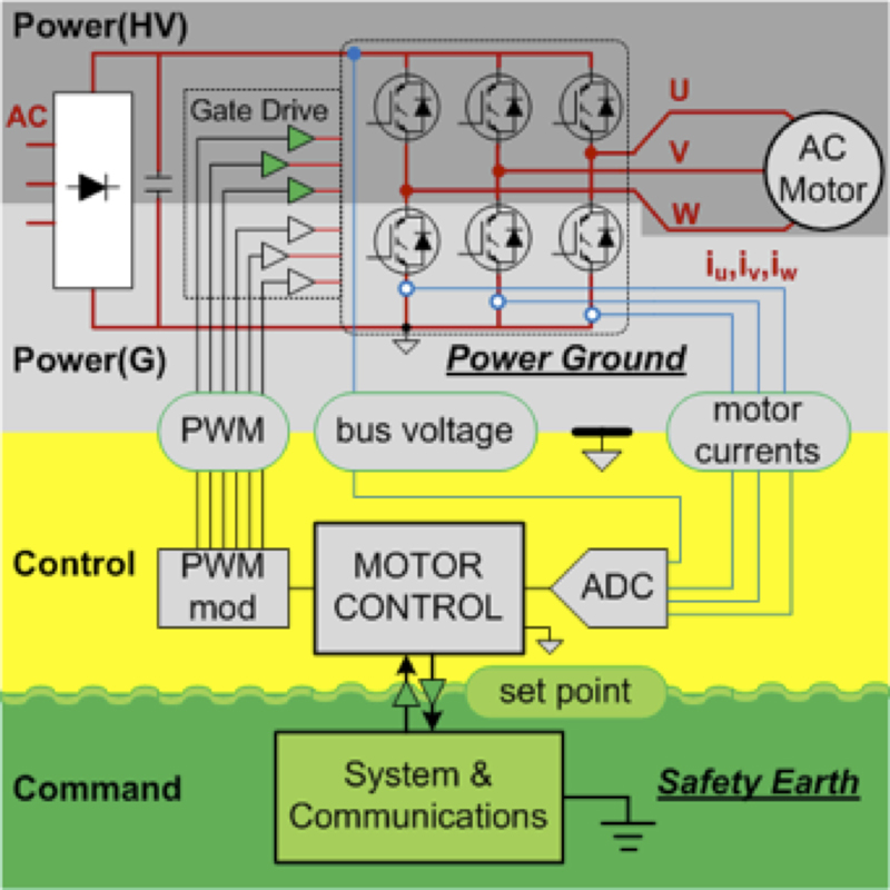
This isolation problem is described in the high level motor drive system diagrams in Figure 1 below showing three power domains: command, control and power. The safety constraint is that the user command circuits must be galvanically isolated from the dangerous voltages present on the power circuit. The architectural decision is on whether to place the isolation barrier between the command and the control circuits or place it between the control and the power circuit.
Click image to enlarge
Figure 1a: Non isolated (a) and isolated (b) architectures in motor control systems
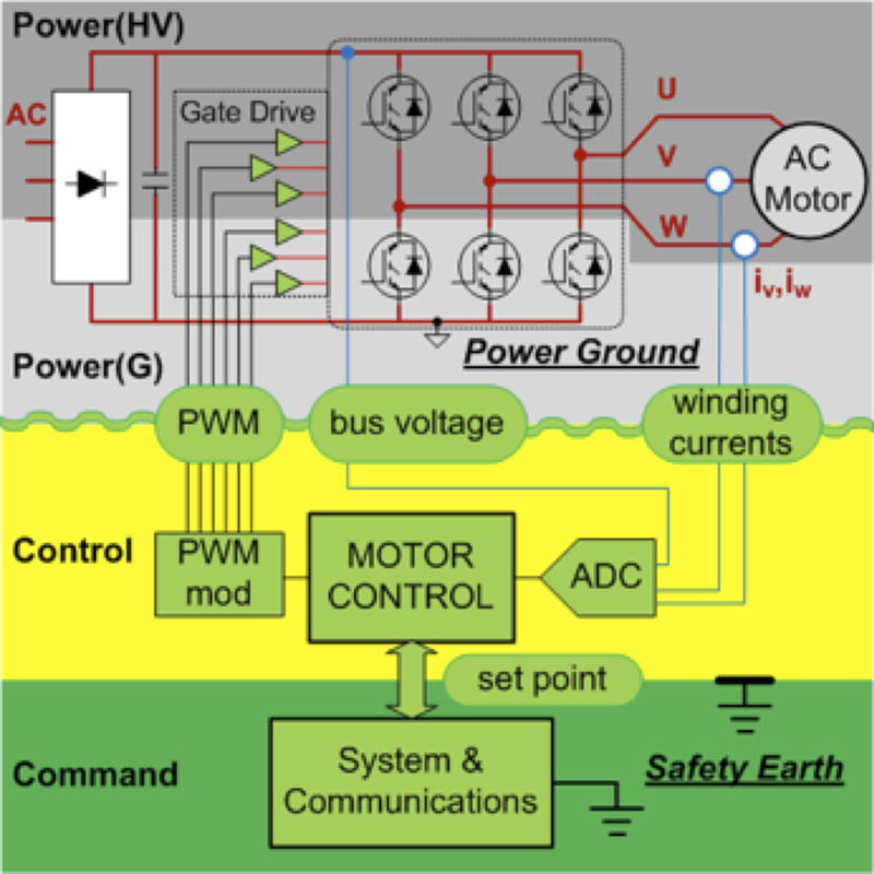
Figure 1b: Non isolated (a) and isolated (b) architectures in motor control systems
The introduction of an isolation barrier between any circuits adds cost and risks signal integrity. The isolation of analog feedback signals is particularly challenging because the classical transformer approach rejects the dc signal component and introduces nonlinearities. Digital signal isolation is relatively easy at low speeds but much more challenging and power hungry at high speeds or when low latency is demanded. Power supply isolation is more challenging than you might expect in systems with three phase inverters because of the multiple power domains on the power circuit. The high side gate drive and winding current signals need to be functionally isolated from control circuit even when the control circuit is referenced to the power ground.
The non-isolated control architecture has a common ground connection between the control and power circuits. This gives the analog to digital converter (ADC) access to all signals in the power circuit. Motor winding current signals referenced to the power ground are available from shunts placed in the lower legs of the power inverter. Three-phase inverters controlled using center based PWM turn on all three low side power switches at the midpoint of the PWM cycle. Thus motor current signals are available from inverter leg shunts by synchronizing the ADC sampling with the PWM frequency.
The drivers for the low side IGBT gates may be a simple non-isolating type, but the PWM signal needs to be isolated from the three high side IGBT gates with functional isolation or level shifting. The complexity introduced by isolation between command and control circuits depends on the end application but it typically involves using a separate system and communications processor. This is acceptable in home appliance or lower end industrial applications where a simple processor manages a front panel interface and sends speed commands over a slow serial interface.
The non-isolated architecture is less common in high performance drives used in robotics and automation because of the high bandwidth requirements for the command interface. However, magnetic isolators capable of data rates over 150MBPS are now available to support non-isolated control architectures in high performance industrial automation applications.
The isolated control architecture has a common ground connection between the control and command circuits. This allows the very tight coupling between the control and command interface and allows the use of a single processor. The isolation problem shifts to the power inverter signals, thus resulting in a different set of challenges. The gate drive signals require relatively high-speed digital isolation to satisfy inverter timing requirements.
Magnetic or optically coupled drivers work well in inverter applications where isolation requirements are quite severe because of the very high voltages present. Motor current feedback is the biggest challenge in high performance drives because high bandwidth, linear isolation is required. Current transformers (CT) are an obvious choice because they provide an isolated signal that can be easily scaled. CT’s are non-linear at low currents and do not transmit the dc level but are used extensively in low-end inverters. CT’s are also used in high power inverters with non-isolated control architectures because current shunt losses become excessive.
Open and closed loop Hall-Effect current sensors can measure dc, so are more suitable for high end drives but suffer from offset. Resistive shunts provide a high bandwidth, linear signal with low offset but need to be matched with a high bandwidth low offset isolation amplifier. Typically the motor control ADC directly samples the isolated current signal but the alternative measurement architecture described in the next section shifts the isolation problem to the digital domain and provides significant performance improvements.
Inverter feedback using isolated converters.
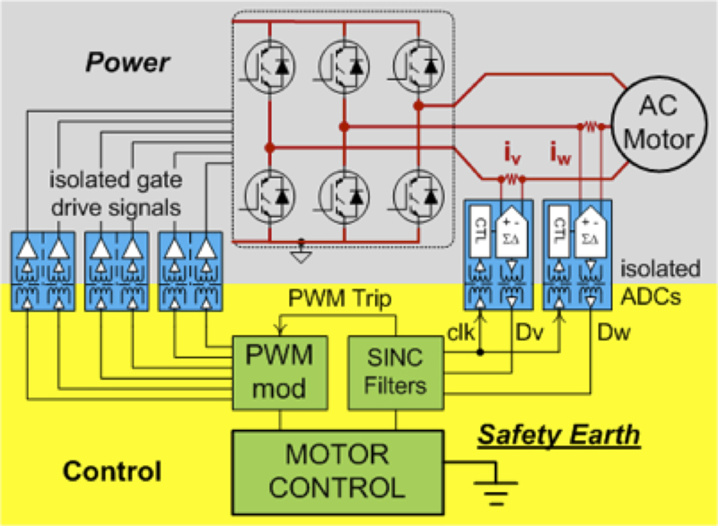
A common approach to improving the linearity of the isolation system is to move the ADC to the other side of the isolation barrier and isolate the digital signal. In many cases this is a serial ADC combined with a digital signal isolator. The specific motor control requirements of high precision for feedback and fast response for drive protection steers the ADC selection to sigma delta. The sigma delta ADC has a linear modulator that converts the analog signal to a single bit stream followed by a digital filter that reconstructs the signal as a high-resolution digital word.
The beauty of this approach is that two different digital filters can be used; a slower one for high fidelity feedback and second low fidelity fast filter for inverter protection. In Figure 2, two isolated ADCs provide current feedback and three isolated half bridge gate drivers support inverter voltage control. The isolated ADC includes a sigma delta modulator that samples the signal across shunts in series with the motor windings and sends a 10MHz data stream across the isolation barrier to a group of SINC filters.
Click image to enlarge
Figure 2: Isolated Current Feedback
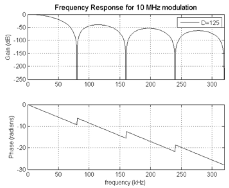
One set of SINC filters provides high-resolution current data to the motor control algorithm, which calculates the target inverter voltages. A second set of lower-resolution filters detects current overloads and sends a trip signal to the PWM modulator in the case of faults. The SINC filter frequency response curve illustrates how appropriate parameter selection enables the filter to reject PWM switching ripple from the current samples (see Figure 3).
Clcik image to enlarge
Figure 3: SINC filter frequency response
Power supply output isolation
The common problem in both control architectures is the requirement to support multiple isolated power domains. This is more difficult if multiple bias rails are required in each domain. The circuit of Figure 4 efficiently produces +15V and -7.5V for gate drive and +5V for powering an ADC, all in one domain using only one transformer winding and two pins per domain. This design makes it possible to use a single transformer core and bobbin to create dual or triple supply rails for four different power domains.
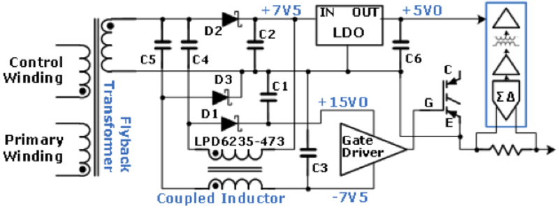
Click image to enlarge
Figure 4 Multi output isolated power from single secondary winding
The two windings in the coupled inductor replace what would usually be added transformer windings. These inductor windings are coupled to the transformer output through capacitors C4 and C5. The upper winding works with C4, D1, and C1 to form a SEPIC output. The SEPIC produces +7.5V, which is added in series with the +7.5V at C2 to produce +15V referenced to output circuit common at the emitter of the IGBT. The lower winding works with C5, D3, and C3 to form a Ćuk output. The Ćuk output produces the -7.5V.
This combination of space and energy efficient power supply design with high speed and stable magnetically coupled isolators supports reduced size and cost in power inverter designs without compromising performance or reliability.