Control and protection rests on measurement precision
Galvanically isolated current transducers address numerous measurement challenges
Designers of solar power—photo-voltaic or PV—generating systems face some of the same problems as their counterparts in any other power-related technology: the need to constantly improve performance, reliability, longevity, and—above all—efficiency. As with any engineering endeavour, improved performance requires with higher-quality and more-accurate measurements.
Of the installations worldwide that are actively feeding power into national and trans-national power grids, around 40% of the total installed capacity is located in Europe and, of that, the largest national installed base is in Germany. In 2011, Germany's cumulative PV generating capacity was just under 25 GW, and in that year its PV power stations generated some 18 TWh for the German grid.
The rapid ramp-up in PV installations can be judged from historical trends: Although connection of solar generating capacity to the grid dates back to the early 1990s, the first GW figure in Germany was reached only in 2004. However, installed capacity grew by 7.5 GW from 2010 to 2011 alone. Other countries have seen PV installations grow at a similar rate.
This almost-exponential growth has been partly driven by generous feed-in tariffs available to those who contracted to provide solar power to the grid, early in the adoption of the technology. In many territories, those initial attractive terms are no longer available, increasing the pressure on system designers to deliver more and more power to the grid from each unit of incident solar radiation and, as systems become more powerful, to do so safely.
PV-system efficiency comes from a number of sources: Semiconductor technologists strive to increase further the conversion efficiency of the basic silicon cells, but much attention focuses on inverter architecture and control. Maximising inverter performance depends on accurate measurements of current and voltage and precision measurements of basic parameters underpin several functions of the solar inverter. The most obvious is fiscal: metering exactly how much billable energy an installation has generated and transferred to the grid in a given period. Next, there is the need to maximise power conversion and, finally, there is a need to monitor possible leakage-current paths to ensure that the solar arrays and their inverters are safe for those working on and around them.
Isolated measurement technology
At all points in the power conversion chain, it is advantageous to carry out current measurements with non-intrusive technologies, that is, with sensors that do not directly connect into the circuit subject to measurement. This provides galvanic isolation from the—possibly very high—potentials of the power-generation path and eliminates I2R losses associated with inserting resistive sensing elements into power paths.
Key to conversion efficiency is maintaining the MPPT (maximum peak power transfer) point. Power output from the PV array is the V-I product of the terminal voltage and the DC current delivered. As with any DC supply that has a source impedance, the voltage drops as the current increases. In solar cells, the relationship is not linear, and varies with the level of light energy reaching cells. The algorithms that control the inverter must constantly adjust the operating point to maintain operation at MPPT. The DC values that determine MPPT change relatively slowly, and moderate measurement precision is sufficient to determine the optimum operating point. Therefore, systems can make these DC current measurements with current transducers that use open- or closed-loop Hall-effect technology.
Various PV installations use a number of inverter designs. Commercial and large PV arrays on industrial or agricultural sites usually series-connect solar panels to deliver a high DC voltage to a high-power inverter with a single feed to the grid. In smaller, typically domestic or commercial installations, work continues to optimise the micro-inverter concept in which conversion to mains voltage is done at each panel. Today micro-inverters are not cost-effective in comparison with traditional technology. Monitoring the aggregate AC fed to the grid in this arrangement presents a separate measurement challenge.
PV installations can make the connection of the solar array through an inverter to the grid either by using a transformer or directly without a transformer. Transformerless installations have no galvanic isolation, with a consequent risk of leakage to earth: Both configurations may also operate with or without energy storage in a battery.
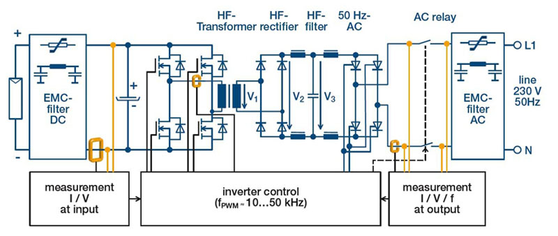
Four main inverter designs are commonly encountered. Two designs use a transformer (at low or high frequency) and two designs are transformerless—with or without a DC chopper or step-up converter. The low-frequency transformer design switches the DC from the PV array at the 50-Hz mains frequency and the transformer (depending on the DC potential available) steps it up to the grid voltage. This provides isolation, eliminates the possibility of DC injection into the grid but implies a large transformer, and is not maximally efficient. This architecture requires measurements at the output of the solar panel and at the AC output to the grid. An alternative is to switch the DC at a higher frequency—tens of kHz—into a step-up transformer, rectify that to an intermediate DC at grid potential, and then use a further switch to generate AC synchronised to the grid. This arrangement is more complex and, depending on the accuracy of the output switch, may inject DC into the grid.
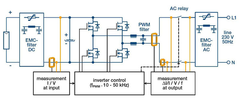
Transformerless architectures switch a DC potential, either direct from the PV array or via a step-up chopper stage into synchronised AC that feeds directly (via a filter) to the grid. As there is no galvanic isolation between PV panel and grid, fault and leakage paths can potentially expose personnel working on and around the panels to dangerous or lethal voltages.
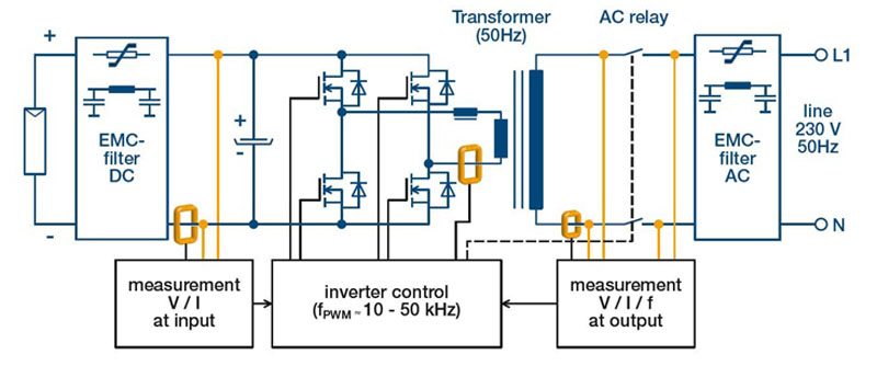
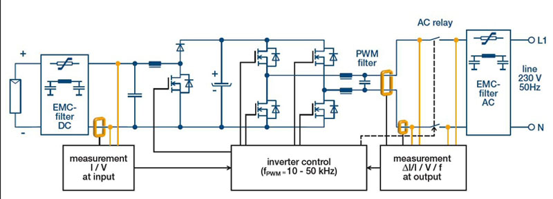
All of these inverter configurations require current and voltage measurements both at the output of the PV array and at the AC output of the inverter, both for control of the inverter and to detect fault conditions (figure 1). Again, open- and closed-loop Hall-effect transducers can provide the necessary accuracy, with fast-response modes providing short-circuit protection.
Click image to enlarge
Figure 1a: Four main inverter designs commonly encountered with their current measurements: Inverter with low-frequency transformer (a), with high-frequency transformer (b), transformerless without DC chopper (c), and transformerless with DC chopper (d).
Click image to enlarge
Figure 1b: Four main inverter designs commonly encountered with their current measurements: Inverter with low-frequency transformer (a), with high-frequency transformer (b), transformerless without DC chopper (c), and transformerless with DC chopper (d).
Click image to enlarge
Figure 1c: Four main inverter designs commonly encountered with their current measurements: Inverter with low-frequency transformer (a), with high-frequency transformer (b), transformerless without DC chopper (c), and transformerless with DC chopper (d).
Click image to enlarge
Figure 1d: Four main inverter designs commonly encountered with their current measurements: Inverter with low-frequency transformer (a), with high-frequency transformer (b), transformerless without DC chopper (c), and transformerless with DC chopper (d).
Addressing exactly this class of application, LEM recently introduced the HO series of open-loop Hall-effect-based transducers. HO series transducers measure up to 25 A—for DC, AC, or pulsed currents—with accuracy as good as 1% at +25 °C. They provide designers with great flexibility as the devices are highly programmable and configurable so that one part can perform multiple roles. A separate over-current-detection function also adds an extra level of safety and circuit protection.
DC-to-grid and leakage detection
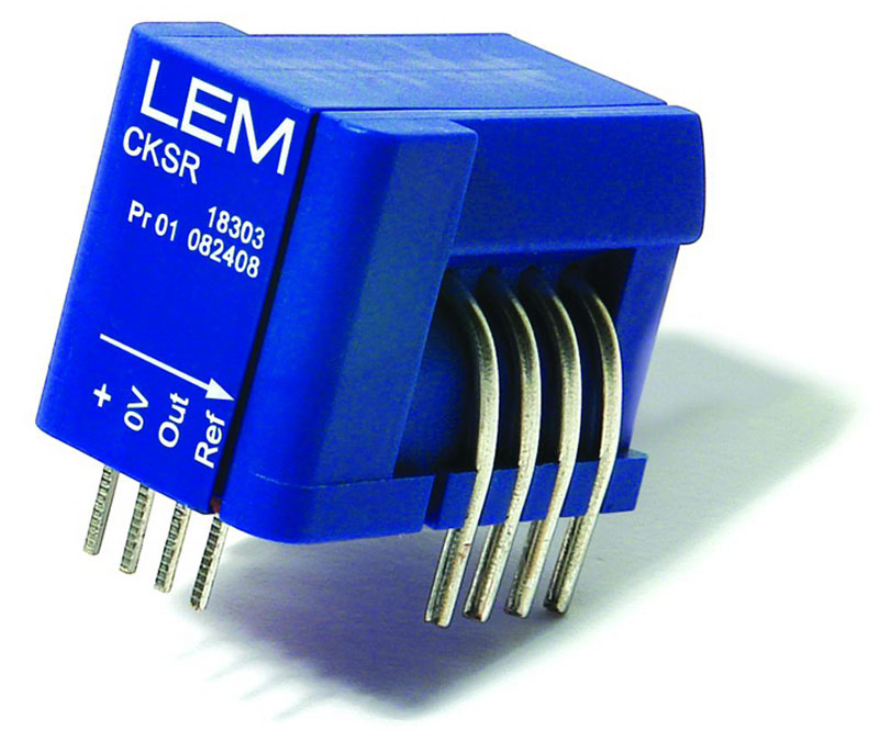
In transformerless designs and in high-frequency transformer configurations, the DC current injected into the grid must be limited to a maximum value of between 10 mA and 1 A, according to different standards that apply in different countries. Relevant standards include IEC 61727, IEEE 1547, UL 1741, VDE 0126-1, and IEC 62109-2. This necessitates use of transducers with very high accuracy and very low offset and gain drifts. The closed-loop fluxgate transducer exhibits these properties (figure 2).
Click image to enlarge
Figure 2: CAS/CASR/CKSR current transducer series use closed-loop fluxgate technology.
Transformerless inverters without galvanic isolation have a potential for leakage currents to occur and it is a requirement to monitor leakage current. Any AC 50- or 60-Hz leakage currents will be small, and must be less than 300 mA, depending on the capacitance due to the solar panel-roof configuration. The system measures the leakage as the residual component remaining from a differential measurement of currents in several conductors.
A person contacting a panel in a fault condition will generate a sudden current leakage variation, and the system must recognisethis condition. In current transducer terms, this requires accuracy and, especially, low offset and gain drifts, to ensure resolution of these small measured currents. Physically, it means the ability to accommodate several conductors, to cater for a single- or three-phase system within the transducer aperture.
Similar demands apply to earth fault-current detection, arising from an insulation defect. The transducer used to measure the earth fault current must be able to measure AC and DC signals as the earth fault current could be AC or DC, depending where the fault (for example, a short circuit) occurs, and depending on whether the PV panel is grounded or not.
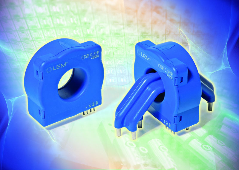
To achieve the targets in terms of accuracy with small currents, LEM applied its closed-loop fluxgate technology and created the LEM CTSR current transducer range (figure 3).
Click image to enlarge
Figure 3: CTSR current transducer series, using closed-loop fluxgate technology, is available with an integrated test winding.
Closed-loop current transducers measure current over wide frequency ranges, including DC. They provide contact-free coupling to the current that needs to be measured in addition to safe galvanic isolation and high reliability. Their closed-loop operating principle, together with sophisticated internal signal processing, yields a transducer that achieves accurate measurement of very small residual DC or AC currents with very low offset and gain drifts over a wide operating temperature range from –40 to +105 °C. The residual-current capability measures the sum of all of the instantaneous currents flowing through the transducer aperture, in single- or three-phase configurations, with a very high overload potential up to 3300 A for a pulse duration of 100µsec, and with a rise time of 500 A/µsec. Conductors may be carrying primary currents of up to 30 A/wire, AC or DC.