Converter and inverter output filtering

Filters are required to minimize EMI and provide reliable operation
Most modern power conversion topologies use switched-mode techniques for highest efficiency and smallest size and cost. Inevitably, switching noise is produced and output filters are required to minimize EMI and provide reliable operation of the power converter and load. This article looks at some filtering techniques that can be used.
Switched-mode techniques for AC-DC and DC-DC power conversion in a multitude of applications inevitably produce some level of output noise that has to be attenuated by filter networks to meet practical and sometimes statutory limits. Similarly, inverters that produce an AC output in applications like motor drives and UPS units need noise filtering to leave the wanted AC output as pure as possible.
For DC, Figure 1 shows a typical output filter circuit of a ‘forward’ or ‘buck’ converter with L1, along with C1, providing energy storage to ‘average’ the transformer rectified waveform to a nominal DC. L1 is typically sized to give a particular peak-to-peak ripple current for fixed switching frequency and duty cycle. This current passes through C1 equivalent series resistance (ESR) producing the required maximum output ripple voltage. The bulk capacitance and equivalent series inductance (ESL) of the component also produce a voltage drop but normally the ESR dominates.
Click image to enlarge
Figure 1: Forward converter output filtering
L1 has to pass the full load and peak ripple current without magnetically saturating so it’s often a large component typically using a powdered iron or gapped ferrite core. Because of its size, L1 often has a high self-capacitance, allowing high frequency noise spikes to pass through. L2 and C2/C3 are therefore added to reduce the noise to acceptable levels. L2 can be quite small as it doesn’t need to store energy but it still needs to pass the full output current without saturating.
Actually, its inductance should only be as high as absolutely necessary, as load current steps will produce unwanted output voltage transients according to E = -L di/dt. If L2/C2/C3 are inside the converter control loop, as would be the case if they are added to a converter with remote sensing, there is a real risk of instability, as the filter adds phase delay to the feedback, so again the inductance should be a minimal value, typically no more than 10% of L1 value and a type with low self-capacitance such as a single winding on a small iron powder toroid or ferrite drum core.
Beating the drum
Drum types do have a large effective air gap round the outside of the winding which can cause unwanted radiation. Ideally, they should be placed with the noisy ‘start’ or innermost winding connection at L1 end to provide a degree of self-shielding. Manufacturers will often mark this connection with a dot. C2 can be an electrolytic type with a relatively high ESR, usefully damping the filter resonance and C3 a small value ceramic type to help attenuation at high frequencies. It has been shown (by Ridley for example) that an optimum design has a relatively low value for C1 and a high value for C2. L1 resonates with the parallel combination of C1 and C2 below the loop crossover frequency and is relatively unaffected by any extra external capacitance.
Peaking of the loop response is compensated for by the feedback loop. L2 resonates with the series combination of C1 and C2 carefully placed above the crossover frequency but below the switching frequency. If C2 is an aluminum electrolytic type, its resonance is normally well damped by its ESR. This arrangement allows feedback loop closure after L2, giving a more accurate DC output while making the circuit relatively insensitive to a customer’s added external capacitance and keeping loop stability.
Other topologies such as ‘flyback’ or ‘boost’ converters have similar filtering requirements after the first energy storage stage.
Common-mode noise
Sometimes common-mode noise on ungrounded converter outputs can be troublesome and can be attenuated with a common mode choke and capacitors to ground. Unlike ‘Y’ capacitors on AC-DC converter inputs there is no maximum value defined by leakage currents but again beware of resonances that might need to be controlled by resistive damping of the choke.
Clearly, ‘less can be more’ with filtering to avoid voltage transients on load steps, potential instability, resonances and of course the degradation of static load regulation due to resistive voltage drops across inductors.
Inverters, with their AC outputs such as are used in motor drives, can have similar requirements for noise filtering with the added complication that the filter also has to pass typically variable, low frequency AC at high current. For a three-phase motor drive for example, a ‘bridge’ of IGBTs or MOSFETs is switched at high frequency with variable pulse width, modulated at the low frequency required by the motor. No energy storage inductor is needed, as the high inductance of the motor itself performs the low pass filter function and it only responds to the modulation frequency.
However, the motor could be some considerable distance away and long cables carrying high current, high frequency square waves with fast rise and fall times cause numerous practical and EMC compliance issues:
• Differential and common mode noise emissions are typically well over international statutory limits set by for example EN55011 or EN61800-3. Screening the motor cables helps but may not attenuate emissions sufficiently and is an expensive solution.
• The cables have inductance and self-capacitance which causes ringing at the edges of the switched waveform. This can be so severe as to multiply up the drive voltage causing breakdown of the motor winding insulation.
• If the switching frequency is within the audible range, which is often the case with IGBTs, mechanical stator vibration causes an annoying ‘whine’.
• A final and insidious effect is common mode noise currents finding a path to ground through the bearings of the motor. An effect called ‘Electrical Discharge Machining’ or EDM causes erosion and bearing failure due to metal transfer between the bearing balls and races. Currents as high as 20 amps have been reported with failures in as little as four weeks after installation.
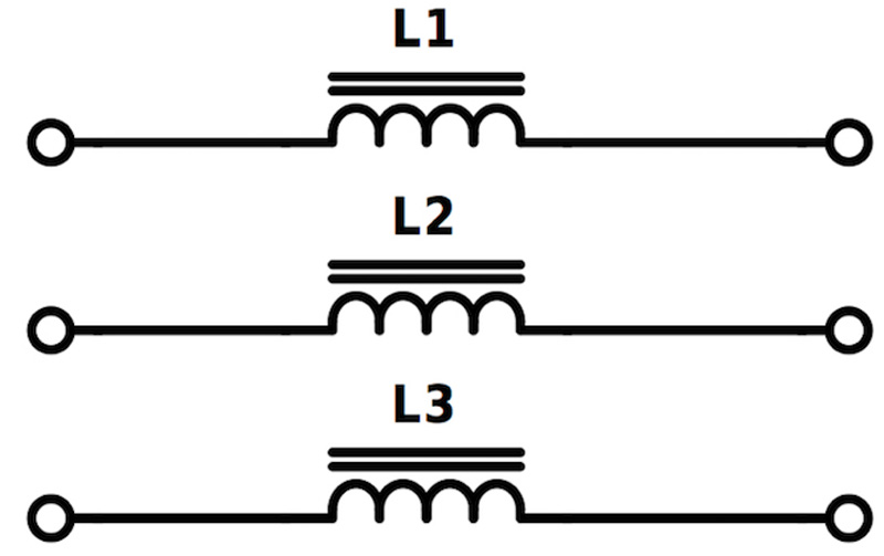
Filters of varying degrees of complexity can reduce or eliminate these effects. Simple differential filter chokes in each line as shown in Figure 2 slow the rise time of the waveform edges reducing ringing and consequent motor insulation stress. Audible noise is also reduced but common mode noise and bearing currents are unaffected. Expensive screened cables and careful grounding schemes can help overcome these shortcomings with cable lengths up to around 50m.
Click image to enlarge
Figure 2: Output or dV/dt choke
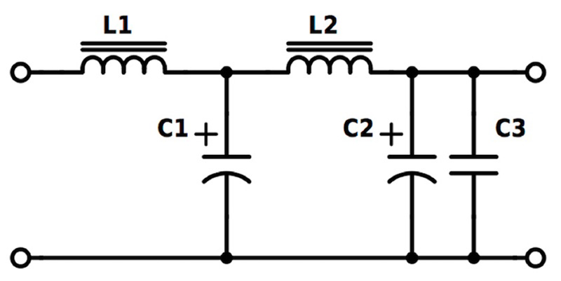
For cables up to around 100m, more complexity is needed, with a filter such as shown in Figure 3. This applies low pass filtering to the power lines with a cut-off somewhere between the PWM frequency and the highest output AC frequency. Large inductors and capacitors are needed, rated for the running current and voltage, adding significantly to the system cost. Again, bearing wear is still a danger and common mode noise is not significantly attenuated so the cable must still be shielded and the longer length of this cable type adds still further to the cost.
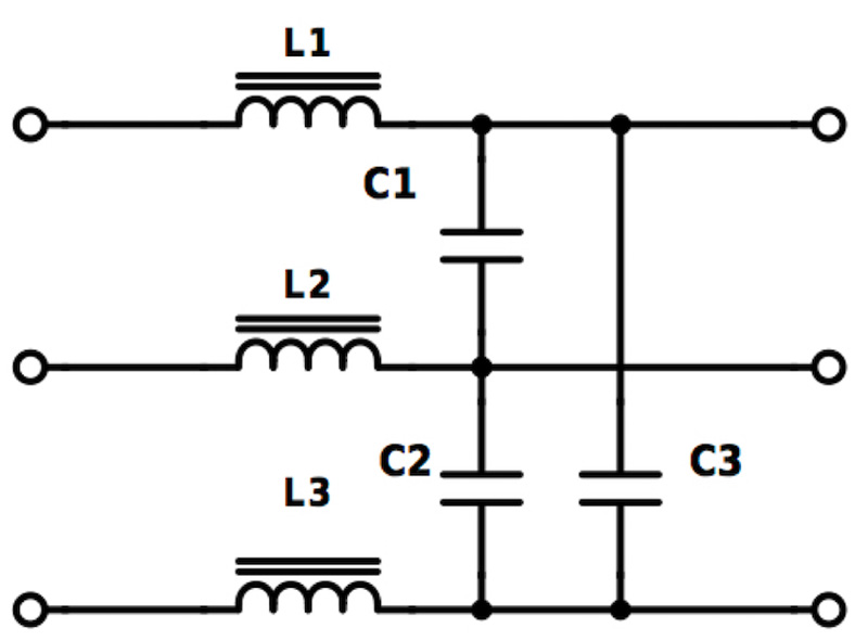
Click image to enlarge
Figure 3: dV/dt or sine-wave filter
So-called ‘sine-wave’ filters with still lower cut-off frequencies carefully selected to avoid distortion of the wanted low frequency AC help differential mode noise attenuation further, potentially allowing cable lengths above 100m, but costs rapidly escalate with still larger capacitors and inductors and the persisting need for shielded cables and precautions against bearing failure.
For example, a commercially available filter called a ‘SineFormer’ as shown in Figure 4, is a more complete solution which includes a common mode choke L4 and ‘Y’ capacitors C4, C5 and C6 along with differential mode filtering L1, L2, L3 and C1, C2, C3. With this filter, dV/dt is less than 500 V/µs, noise is reduced, EMI is largely attenuated and bearing currents are diverted away to local ground leading to extended motor life.
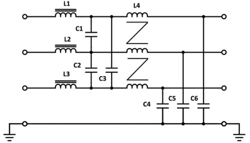
Click image to enlarge
Figure 4: TDK EPCOS SineFormer filter
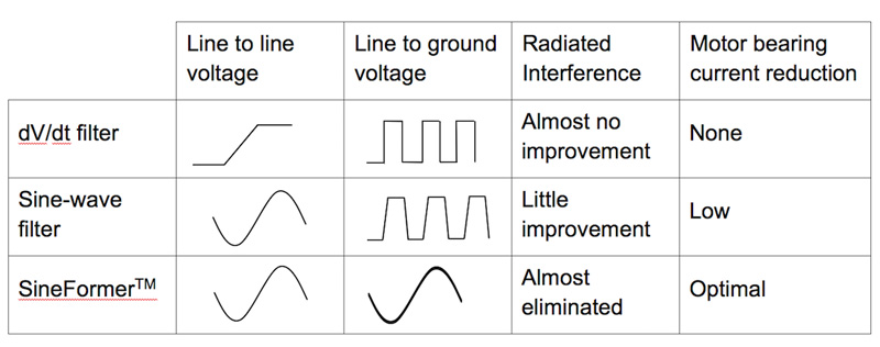
Perhaps the biggest advantage is that an unshielded cable can be used meeting EMC specifications up to perhaps 1000m with huge consequent cost savings. Although the filter has significant cost as a component, the makers TDK-EPCOS have calculated that it can give an overall system financial saving for cables in excess of 50m when the cost of shielded cable and its complex termination is factored in. Of course, if the possibility of early motor failure is considered with associated costs of downtime and replacement, the choice is clear. Figure 5 gives a summary of the performance of the various filter types considered.
Click image to enalrge
Figure 5. Summary of filter performance
TDK-EPCOS has a range of EMC filtering components suitable for switched-mode converter DC and AC outputs including powder and ferrite cores, wound inductors, capacitors and filter blocks including the SineFormer series. The company encourages consultation to help designers reach an optimum solution with TDK-EPCOS components.