Direct liquid cooled power modules in converter solutions
Modern wind turbines are being designed for a lifetime of 15-20 years. In the special case of wind power, the turbines are expected to run 24 hours a day, 365 days a year when the wind allows. This corresponds to 150-180.000 hours of service which again is 10-20 times the lifetime expectancy for typical automotive applications and 3-5 times the expectancy in industrial applications. To secure sufficient reliability over the expected life of any such critical system, calls for an in depth understanding of the relevant failure mechanisms and mission profiles of the specific application. Today's major converter systems can from a power-cycle point of view be boiled down to three basic topologies: Doubly Fed Induction Generator (DFIG), Full Conversion with Gear (FC) and without gear known as Direct Drive (DD). The different topologies are characteristic by the dominating frequency regimes they are operating at. The Grid side again differs as it is operating at rated frequency.
Further, the different topologies depending on control strategies and generator design will result in different sharing between diodes and IGBTs and thereby influence the resulting fatigue effects. The dominant failure mechanism in power modules for wind applications for example, is related to active power cycling of the power semiconductors occurring during operation. Depending on the converter topology chosen this active power cycling will result in temperature swings of the wirebond - Silicon interface; put simply the size of the temperature swings as well as the absolute temperature levels determine the life time of the power module. Since the number of temperature cycles seen in wind applications is several orders of magnitude larger than typical seen in industrial- or automotive (e.g. HEVs) power modules it is obvious that an extremely highly efficient cooling of the power modules is needed. ShowerPower�® is a direct liquid cooling concept that ensures homogenous and highly effective cooling across large power modules and of systems of large power modules.
Liquid cooling of power electronics has been around for many years, in some segments more than others. The acceptance for applying liquid cooling varies from business segment to business segment: the automotive industry for example has always used liquid cooling for cooling the combustion engines so the idea of cooling power electronics in an automotive application is not at all un-nerving for these design engineers. In other segments, however, the idea of having water flowing through power electronic assemblies can be disturbing. The largest obstacle for applying liquid cooling has, in the past, been the high cost and the limitations in performance that confines the usability to more exotic applications where no alternative exists. These limitations being large temperature gradients across the cooling areas and high pressure drops in the coolers that make large/expensive pump systems necessary. Here, the concept from Danfoss for applying liquid cooling is described, combining high performance, very low cost and ease of implementation even in thermo-mechanical assemblies with complex geometries.
Basically two types of liquid coolers exist: Closed coolers, where devices to be cooled are assembled in a dry fashion eliminating the problems associated with spillage of coolant, and open coolers, where the devices to be cooled are assembled on a so-called "bathtub" through which the coolant flows and cools the backside of the device.
Cold plates are often aluminium plates, extruded or machined, and some of them have copper tubes inserted in grooves in the plate. Other versions consist of two metal parts, machined or extruded, that are joined together (normally using welding or active brazing) and the coolant is then guided through channels defined between the two parts. The first improvement by going the direct liquid cooled route is the elimination of the thermal interface material (TIM) which is responsible for 30-50% of the thermal resistance between junction and coolant. Secondly the inherent reliability problems related to pump-out and dry-out effects of TIMs are gone. Thirdly ShowerPower�® enables cooling of standard power modules with flat base plates thus allowing dual sourcing of the power modules, an increasing prerequisite in the wind industry. Direct liquid cooling of the power modules using ShowerPower�® enables more compact, lightweight and cost effective designs compared to traditional cold-plate based solutions, partly due to the higher level of design freedom given to the designer. As an example, ShowerPower�® has been demonstrated to reduce the number of power modules in modern wind turbines converters by up to 50% compared to traditional cold plate solutions. This is due to the improvement in thermal performance over the cold plate.
All liquid coolers suffer from the inherent problem of cooling, where the heating of the coolant is reflected back into the power device resulting in a temperature gradient. The other major drawback of these coolers has been the high cost. Cold plates are still expensive due to the precise machining operations in the manufacturing process while the traditional pin fin coolers also feature high manufacturing costs; a typical pin fin baseplate can cost five times more than the standard flat baseplate.
As previously discussed traditional liquid cooling systems all feature a liquid flow along the surface to be cooled, this will always create temperature gradients in the surfaces to be cooled because the liquid is heated up and this temperature difference is reflected back into the power device.
The original idea was to cool perpendicularly to the surface to be cooled, thus the name ShowerPower, but in contrast to existing spraying or jet impingement systems the idea is to get rid of the coolant before it starts creating large temperature gradients along large portions of the device to be cooled where a number of nozzles guide the coolant to the surface to be cooled and a corresponding number of outlet nozzles lead the coolant away before the coolant has travelled large distances on the cooling surface. The inlet nozzles are supplied from an inlet manifold situated between the two plates and the outlet nozzles are connected to an outlet manifold situated between the bottom plate and the bottom of the bathtub. Inlet and outlet manifolds are connected to the main inlet and outlet connectors of the bathtub. In this way parallel cooling is achieved and identical cooling is achieved everywhere on the surface to be cooled. The next step in the design has been to simplify the structure of the plastic parts. The double-plate design discussed until now demands at least two plastic parts, which are to be joined, but it is possible to realise the functionality using one plastic part only. The inlet- and outlet manifolds are now interlaced instead of sandwiched, see the figure below.
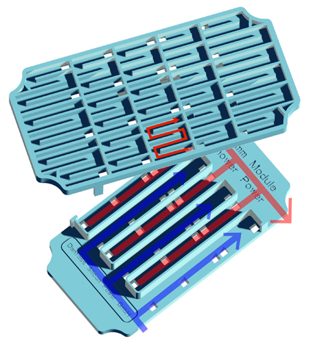
The areas to be cooled can be of any size and shape. Non-planar geometries and surfaces are easily realized. Tailored cooling is also possible, i.e. if a specific hot spot needs extra attention in a power module, the nozzles are simply tailored in order to cool more effectively locally.
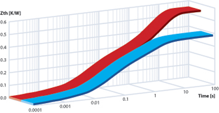
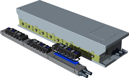
Comparing the thermal step response curves (heating curves) shows why the two cooling solutions perform differently: The two curves are almost identical until roughly one second indicating that for shorter temperature swings the sizes of the swings will be the same (only dependant on the internal thermal capacity of the module), but the average temperature where the swings occur will be much higher for the cold plate because of the much higher steady state thermal resistance for the cold plate. For cycles with periods longer than one second the size of the temperature swing too will be larger for the cold plate. Therefore a coldplate solution requires much more silicon in order to offer the same power cycle capability as direct cooling with ShowerPower�®. Examples of Danfoss power stacks are shown below. Both stack designs are based on the P3, 1700A/1000V, module placed on a ShowerPower�® cooler.
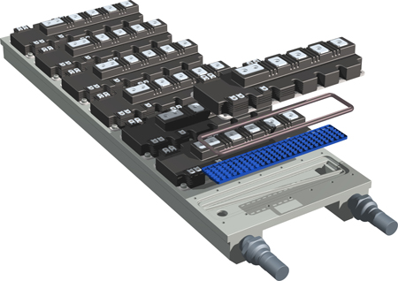
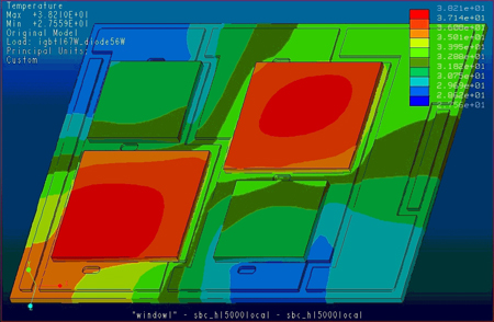
The earlier example features three P3 modules placed in a row, here the power module assembly is shown in the foreground; the other example shows a setup having seven P3 modules. The heat transfer coefficient, or convection coefficient, which is a measure of the cooling efficiency (the higher the better) as function of volume flow-rate (ethylene-glycol/water 50%/50%). The ShowerPower cooler is proven to be the same or even more effective than the pin fin cooler. The homogeneity of the cooler means all the cells will have the same pressure drop. Additionally, the inlet-outlet manifolds have the same pressure throughout their volumes, thus the hydrothermal performance is indeed homogenous across the whole of the cooling area. The homogeneity of the ShowerPower cooler has been compared with that of the standard pin fin cooler using thermography. A significant temperature gradient was observed in the pin fin case, whereas there was no detectable gradient in the ShowerPower case.
As mentioned, it is easy to adapt to special cooling demands e.g. if a power module has components that run especially hot. As a special case of the tailored cooling it is straightforward to cool only at the component positions. In an experiment with a power the temperature gradient across one of the IGBTs was 20K when cooling underneath the whole substrate area.
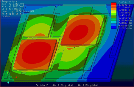
The RthJA was 0,26K/W. By localizing the cooling the temperature gradient across the chip is reduced to 2K, the trade off was that the RthJA is increased 50% to 0,38K/W.
Several approaches have been investigated in the quest for improving the performance of the ShowerPower cooling principle to improve thermal performance without increasing the pressure drop. One approach was to introduce small by-pass gaps between the walls of the meandering channels and the baseplate of the power module, allowing fluid flow over the top of the walls of the meander cells. The result was that the pressure drop was reduced; this was expected since some of the fluid had to travel a shorter distance through the cooler. Another effect though, was more surprising: by introducing the small gap of 0,25mm the thermal performance improved 25-30%. Overall, the effect was extremely positive and improved thermal performance at a lower pressure drop.
Due to the homogeneity of the cooling all the IGBT chips inside the modules will have the same junction temperature (and all the diodes will have the same temperature), this eliminates the critical lifetime-limiting hot spots, and facilitates the paralleling of the many individual chips. The compact cooler opens up for larger design freedom in the power train to fit the needs of the individual application. ShowerPower from Danfoss is the key to reliability and longevity in the vital high power systems upon which our community is becoming increasingly dependent. siliconpower.danfoss.com


