Analysis of power supply single speed air-mover & entire enclosure system fan
Figure 1
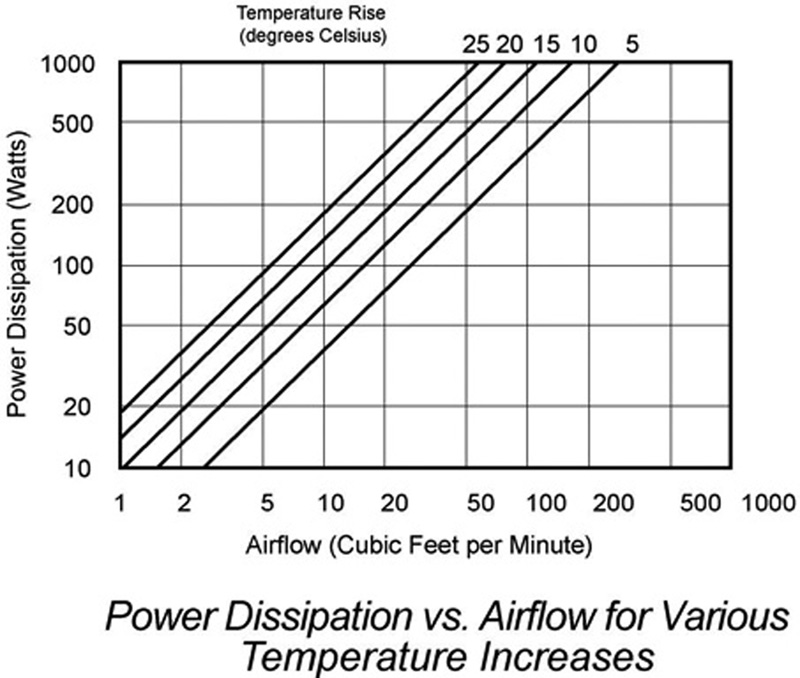
The need for forced-air cooling should be assessed at an early stage in system electronics enclosure design. The full range of implications needs to be considered in detail for a successful outcome. Typical densely packaged electronic systems and power supplies use a fan for forced-air cooling. Power supply cooling technology often employs computer electronic thermal management techniques including the following: • Thermal vias • MOSFET surface mount packaging • Power transfer by bonding exposed leads to a thermal plan on printed circuit boards • Metalized substrates • Isolation materials • Laminar bus bars • Direct bond copper • Isolated metal substrates • Glass on epoxy • Thick film on ceramic • Copper on ceramic The need for forced-air cooling should be assessed at an early stage in system electronics enclosure design. It is important that the systems designer have electrical, mechanical, magnetic, thermal, acoustic and chemical knowledge to design good airflow to heat-generating components. Critically, the design must allow adequate space and power for cooling components. The first stage in designing a forced-air cooling system is to estimate the required airflow. The primary variable depends on the heat generated within the enclosure and the maximum temperature rise permitted. AC input power is a good initial estimate of the power dissipated within the enclosure. In estimating the power dissipated within a system, the power dissipation figure used should be a worst-case estimate for a fully loaded system. Airflow calculations using heat dissipation and temperature rise for system impedance characteristics The required airflow is obtained either by calculation or from a standard graph. The equation for calculating the required airflow through an electronics enclosure is as follows: Q = 1.76 W / Tc Where: Q = Airflow required in CFM W = Heat dissipated in Watts Tc = Temperature rise above inlet temp °C For example, what airflow does a system need that dissipates or consumes 300 Watts, allowing only a 10 degree C rise? The above equation results in 52.8 CFM. This equation can be graphed on the following logarithmic chart (Figure 1) with the vertical axis representing the heat to be removed and the horizontal axis representing the airflow; both axes are logarithmic. The sloping lines define the temperature rise in degrees C.
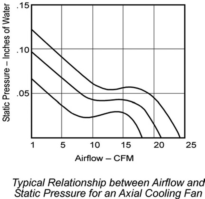
System impedance Because obstructions in the airflow path cause static pressure within the enclosure, determining the actual airflow needed by a fan mounted in an enclosure is more complex. Figure 2 shows the nonlinear relationship between airflow and static pressure for a typical fan. Obstructions should be minimized to achieve maximum airflow. Air guiding devices, in the form of baffles, may be necessary to direct the airflow over the components that need cooling.
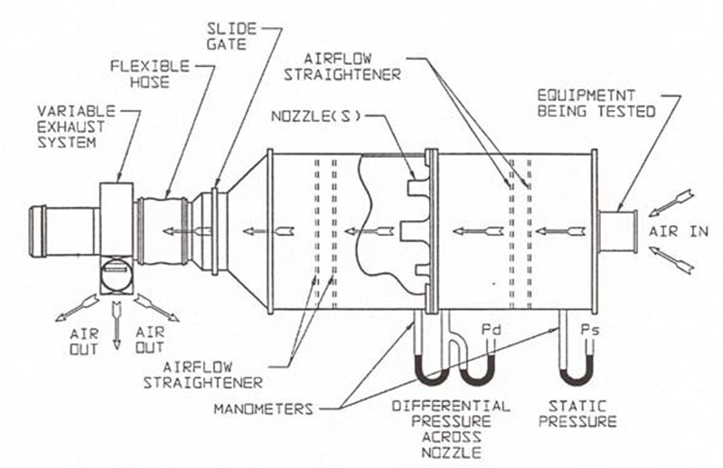
Static pressure for an axial cooling fan The experimental method of finding airflow through an enclosure is in accurate and time-consuming. An airflow chamber is required, as shown in Figure 3, and care must be taken to simulate accurately the electronics enclosure being tested. The following rules-of-thumb can be used to estimate airflow resistance: • An empty enclosure usually reduces airflow by 5 to 20% • A densely packed enclosure reduces airflow by 60% or more • Most large tower computer electronic enclosures have a static pressure of between 0.05 and 0.15 inches, H20. Assuming a dense package, the fan in the previous example should be capable of delivering 80 CFM in free air, instead of 52.8 CFM. Designers need to be aware that fan manufacturers use the most optimistic figures to represent their products. Intake, exhaust, and baffles System designers have the option of mounting an air-cooling device to exhaust warm air from the enclosure or to blow cool air into the enclosure. Theoretically, the same volume of air is used to dissipate heat. However, depending on the application, each arrangement has advantages and disadvantages. Incoming air flows in a laminar fashion to allow for a uniformly distributed airflow in the enclosure. This is important in eliminating stagnant air and possible hot spots. Air exhausted out of an enclosure is turbulent. Heat dissipation in a turbulent airflow could be double that of a laminar flow with the same volumetric flow rate. Turbulent airflow is desirable. The turbulent airflow near a fan exhaust is limited to a very short distance, depending on the size of the fan. This is why it is desirable to have a heat sink, or the components that need most cooling, immediately at the fan output. Developing a well-defined airflow path through the entire enclosure is extremely important. The air-vent area should be 50 percent larger than the fan opening. This is why most system exhaust fans are placed at the output of a computer or power supply enclosure. Recirculation is desirable for very large computer server systems. However, in most small electronic enclosures, air recirculation should be avoided. With small form factor fans, all of the airflow can be lost because of recirculation problems. Baffles, shrouds, or ducting systems are often necessary to eliminate recirculation of the same air and to direct air onto, or away from, hot spots. Airflow will always take the path of least resistance. Physical subassemblies and components within the enclosure, such as large capacitors and circuit boards, can be intelligently positioned to direct the airflow to places that require cooling. Natural convection cooling should take precedence in electronic enclosure designs. Therefore, a systems designer should place warm components above cool components. Fans used to exhaust heat from electronics enclosures reduce the pressure within the enclosure and dust is drawn in through all the vents and openings. Dust accumulation can produce many problems. Because exhaust fans tend to operate under hotter conditions, exhaust fans can have only half the life of an intake fan.
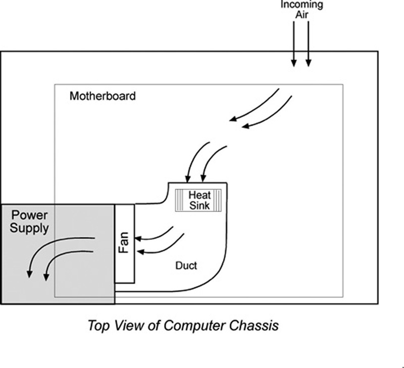
In general, it is best to use a single fan that ventilates an entire enclosure, including the power supply, as shown in Figure 4. Notice that this system recommendation uses a baffle ducting system, which evacuates hot air from the electronics enclosure while pushing air through the power supply. This is the most economical approach. A variable speed fan is recommended in order to reduce noise and optimise energy efficiency. However, most power supply fans simply run at a fixed speed. Applying additional airflow through the power supply will not adversely affect it. With a variable speed fan, the fan circuit automatically controls the speed. For example, JMC has recently patented a software controlled SMBus/I2C, OS or BIOS-configurable intelligent fan known as the �Intellifan'. The Intellifan is independent of analogue circuitry and imprecise thermistors. As the temperature changes the fan speed is adjusted precisely, ensuring optimum airflow at all times. www.cyntechcomponents.com


