Creating a USB Li-Ion battery boost charger
With a method for monitoring the input voltage to ensure that the supply remains in compliance
Oftentimes, designers of digital cameras, mobile devices and other consumer electronics choose to power their device from two, series-stacked, Lithium-Ion (Li-Ion) batteries, yet still desire the capability to charge from a 5-V universal serial bus (USB) port. Boosting a 5-V USB input to charge two series-stacked Li-Ion batteries can require using specialized ICs.
However, this task can also be accomplished using a simple op amp circuit and an off-the-shelf boost regulator. In this article, I present a method for monitoring the input voltage to ensure that the USB supply remains in compliance, and to monitor the charge current so that the battery’s requirements are not exceeded.
A popular port
Charging batteries from a 5-V USB port is a very popular method for charging batteries in personal electronic devices. This is a relatively straight forward task, particularly if the device being charged is powered by a single Li-Ion battery. The maximum voltage on a typical battery is 4.2 or 4.3 V, and the output of a USB 2.0 port is generally above 4.5 V. In this instance, a standard linear or switching buck battery charger is sufficient.
Occasionally, a device requires more power than can be delivered by a single battery. Now the designer must decide if he wants to configure the batteries in the pack in a series or parallel configuration. Although a parallel configuration allows a buck-style USB charger to be used, often it is more convenient or appropriate to configure the pack in a series configuration.
Once a designer selects a series battery configuration (2S or more) and decides to charge from a 5-V nominal USB source, the challenge becomes how to best (and most efficiently) boost the supply voltage. The goal is to not overload the USB source while maintaining an appropriate charging profile for the battery.
Types of USB ports
Although all USB 2.0 connectors look identical physically, electrically there can be differences from port to port. The charger needs to work properly regardless of which type of USB source it is connected.
There are three possibilities:
1. Standard downstream port (SDP) – can supply a minimum of 4.75 V at up to 500 mA when properly configured.
2. Charging downstream port (CDP) – must be able to supply at least 1.5 A at 4.75 V
3. Dedicated charging port (DCP) – must be able to maintain its output to 4.75 V minimum at 500 mA minimum, but may (and most likely will) be able to supply more current before its output voltage collapses.
Since the SDP needs to be configured in order to allow it to provide more than 100 mA of output current, one can assume that the USB-compliant system will employ some sort of microcontroller that the charging system may be able to use as well. Nevertheless, the ideal system must be able to monitor both input current and input voltage to allow operation within a broad range of USB 2.0-type supplies.
The DCP is particularly challenging in that it is guaranteed to maintain a 5 V nominal output until the current draw exceeds 0.5 A, after which its output voltage is allowed to drop below 4.75 V. In this situation, the charger must be capable of dialing back the charging current, if the input voltage happens to fall out of regulation (5 V nominal).
Beyond USB 2.0, USB Type-C adds additional capability as well as a different style connector. A 5-V source is certainly still a possibility with a USB Type-C connector. In this case, the battery charging approach provided could be used. USB power delivery with potential access to a 20 V power supply may alleviate the need for a boost charger.
Charging a battery
A charger needs to support the required charging profile of a Li-Ion battery. A good charger will have a constant current (CC) a portion of charge time. This occurs when the battery voltage is below its fully-charged voltage. When the battery approaches a fully-charged state, there is a period of time when the charge current tapers off. During this time the voltage is regulated rather than the current. It remains in this constant voltage state until the charge is terminated. The determination of when to terminate a charge is often made by a battery fuel gauge. A typical charge profile is shown in Figure 1.

Click image to enlarge
Figure 1: Typical charging profile of a battery charger
The challenge for a boost charger is that it needs to:
a. Regulate the charger output voltage so that it does not exceed the pack’s fully-charged voltage
b. Limit the current draw from the USB supply to ensure that the voltage does not collapse (in other words, maintains at least 4.75 volt output)
c. Regulate a peak-charging current per the battery’s maximum charge current capability
Charge termination may be a concern for the battery charger as well. However, there are times when it is acceptable for the battery’s fuel gauge (rather than the charger) to determine when to terminate a charge. My example design relies on the battery fuel gauge to terminate charge.
The design
The solution implemented for this study was based on an off-the-shelf boost regulator. The ideal regulator must be able to handle the switch current to allow boost operation while providing the desired maximum battery-charging current. It also needs to handle a 5-V USB input and be able to support a switch voltage, allowing the output to reach the required, fully-charged battery voltage.
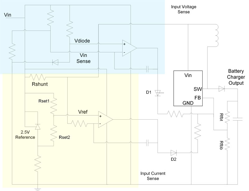
Finally, implementation relies on a resistor selectable output voltage so that the feedback (FB) pin can be easily manipulated by external circuitry. The peak (fully-charged) pack voltage will be set by this device and its output voltage set point. Figure 2 is a schematic of the design used to test this approach. I selected RFBT and RFBB to regulate the output at the maximum desired battery stack voltage.
Click image to enlarge
Figure 2: Boost regulator with VIN and IIN detect circuitry
To control the battery-charging current, as well as the load on the USB port, the circuit monitors the voltage drop across the shunt resistor (Rshunt) and compares it to a reference voltage generated by a 2.5-V shunt regulator. If the voltage drop across the shunt resistor indicates that the current draw is exceeding the current set point (set by Rset1 and Rset2), a signal is injected into the boost regulator’s feedback node. This signal acts to dial back the output voltage, thereby reducing the charging current. To select different maximum currents – if perhaps your product will be exposed to USB ports of differing capabilities – you can use a microcontroller to multiplex in different resistors at position Rset1.
The voltage regulation circuit works similarly. As a cost savings, I used a forward-based diode to provide a ~ 0.6 V reference. However, a shunt reference is preferred in this position as well. In this portion of the circuit, I used an op amp to ensure that the input voltage does not fall below 4.75 V. This indicates that the USB source is overloaded, as in the case of a DCP charger without a known current capability. In this case, if the input voltage drops too low, the op amp injects a signal into the regulator’s FB node – again dialing back the charger output. This action lessens the demand on the USB supply and allows it to come back into regulation.
Diodes D1 and D2 are in place to isolate the circuit from the regulator’s FB node when voltage and current are in line and the op amp outputs are being driven low. With the op amps out of the circuit, the regulator simply regulates the battery voltage at a constant voltage, as is typical during the constant voltage portion of the charge cycle.
This scheme works well for benign loading of the battery. Under heavy pulse loading, the current and/or voltage could exceed the set points, as the bandwidth of the system is relatively slow.
A simple solution
This is a low-cost, easily implemented approach to charging series stacked Li-Ion batteries from a 5-V source. Rather than using dedicated ICs that are still relatively uncommon, this approach requires using only two, readily available components: a boost regulator and a dual-op amp.