New Sensing Technology Improves BMS Performance
Figure 1: 4p108s Battery Pack Configuration
Electromobility in the form of electric bicycles or Electric Vehicles (EVs) has gained popularity as gasoline prices increase and the public becomes environmentally aware. These electromobility vehicles consist of an electric battery for energy storage, an electric motor for movement and a controller to manage the system; all requiring a method for sensing and measuring current. Since the current required to propel an EV can be in the order of 100’s of amps, current measurement can present a challenge for safety, accuracy, and thermal management. This article discusses current measurement techniques with an introduction to a new magneto-resistive sense technology.
Accurate measurement of large direct current (DC) is necessary for EVs since they have high power and energy demands. This energy is realized by the parallel/serial interconnection of lithium-ion cells making up the battery pack. The cell configuration is in the form of ‘xpys’ where ‘x’ are cells in parallel and ‘y’ are cells in serial connection. For example, the Tesla Model S battery pack is 74p96s, Nissan Leaf (2p96s) and Audi e-tron 55 (4p108s). The battery for the Audi e-tron has a nominal voltage of 396 volts (3.66V x 3s x 36 modules) and a capacity of 240Ah (4p x 60Ah) for a total of 95kWh (Figure 1).
An EVs battery pack is typically designed for a voltage range between 300V to 450V to balance the energy needs between safety and a component’s power handling capability. Higher voltages result in stringent requirements for creepage and air gap distances, insulation material thickness and requires components capable of withstanding high voltages. Lower voltages require higher currents for the same power resulting in the need for higher gauge conductors that increases the cost and EV weight.
The heart of an electric vehicle is the battery system consisting of a rechargeable lithium-ion battery and a battery management system (BMS) to maximize battery use and safety. The BMS can be defined as any electronic system that manages a rechargeable battery pack by maintaining operation within its safe operating area (SOA), monitoring its state, calculating secondary data, reporting that data, and balancing the individual cell voltages.
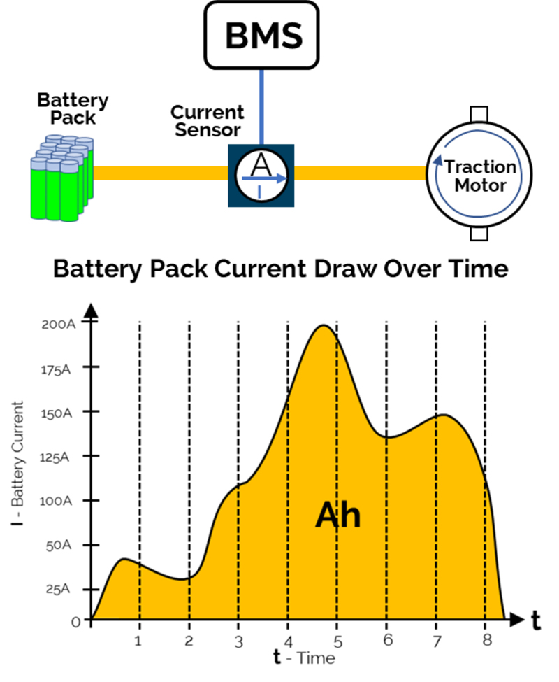
A BMS’s primary function is to manage the battery state by monitoring its voltage, current and temperature to keep it operating within its rated safe operating specifications. A battery’s state of charge (SOC) and state of health (SOH) calculations are based on monitoring the battery’s current consumption profile over time (Figure 2).
Click image to enlarge
Figure 2: Battery Pack Current Sensing Over Time
Therefore, accurately monitoring a battery’s current not only helps extend its operating life and improve driving distance it also alleviates ‘range anxiety’ by keeping the driver informed on the remaining battery capacity.
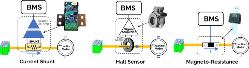
A standard coil transformer can accurately measure current, but it is limited to AC current, unusable for an EV battery system which is fundamentally DC. The BMS can only use DC current sensors such as current shunt, Hall effect or the latest magneto-resistance current sensor, Figure 3.
Click image to enlarge
Figure 3. Types of Current Sensors for EVs
A current shunt is simply a high precision, low value, high power resistor. The battery current is routed through the shunt, which results in a voltage drop proportional to the current. The voltage across the shunt needs to be amplified, isolated, and measured to derive the proportional current.
The advantage of a current shunt is it doesn’t exhibit an offset with no current flow. However, the required isolated amplifier will introduce an offset and the shunt resistor will dissipate power according to the equation P = I2R. As current (I) increases so too does the temperature. Since the resistance values are in the order of a few μΩ, operating temperature variations will slightly change the shunt resistance leading to measurement errors.
A Hall effect sensor detects and measures the magnetic field generated around the current carrying conductor and outputs a voltage proportional to the current flow. The advantage is that magnetic field sensing by default provides a galvanic isolation between the sensor and the battery system. The disadvantages include a high offset (which varies with temperature), nonlinearity, and magnetic hysteresis (large currents in one direction affects the zero offset). As the sensor accuracy degrades the BMS will need to periodically perform calibrations to maintain sensor performance.
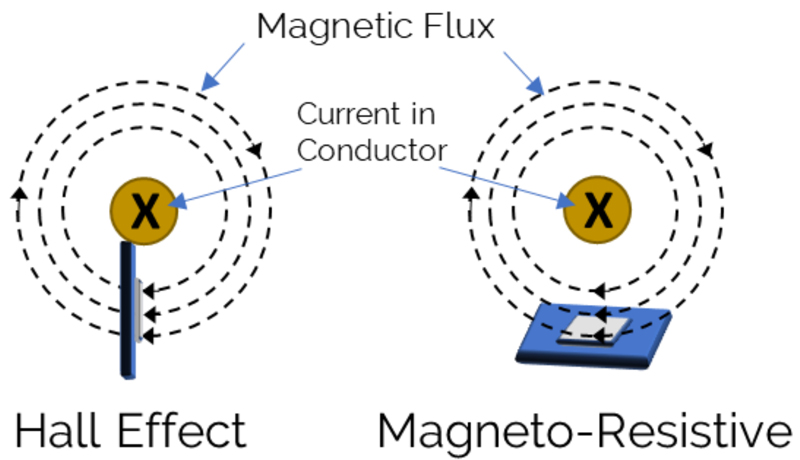
Magneto-resistance sensors similar to Hall sensors provide contactless current sensing by measuring the magnetic field generated by a current carrying conductor, Figure 4. The basic principle underlying the Hall effect is the Lorentz force, a Hall plate will output a voltage in the presence of a perpendicular (Z-axis) magnetic field. A magneto-resistance sensor uses the fact that the resistance of a ferromagnetic alloy will change in the presence of a magnetic field. The resistance is smallest when the magnetic field is at a 90-degree angle (Z-axis) and highest when the flux lines are horizontal (X,Y-axis). In general, magneto-resistance sensors have excellent Signal-to-Noise Ratio (SNR) with a higher sensitivity and accuracy than Hall sensors.
Click image to enlarge
Figure 4: Contactless Current Sensing
These sensors are constructed from resistive ferromagnetic elements which are configured in a Wheatstone bridge to maximize sensitivity, lower power consumption, minimize thermal instability and achieve better linearity. A magnetic field changes the resistance values causing a bridge imbalance and generating an output voltage proportional to the strength of the magnetic field.
Contactless current sensors will detect magnetic fields from nearby current carrying conductors, making them susceptible to stray magnetic fields. These stray magnetic fields can be produced by current conductors or inductive motor loads and will contribute a serious source of measurement error unless careful precautions are taken to guard against them.
A popular solution is to shield the sensor with expensive metal alloys having a high magnetic permeability. These costly and bulky alloy shields don’t block or eliminate the magnetic field but instead redirect the field to keep it at a known distance from the sensor. If not properly sized or spaced, this shielding can equally affect the magnetic field generated by the current conductor and therefore has the potential to distort its measurement.
It is more cost-effective and preferable to use a sensor with built in immunity to external fields. The ideal sensor is constructed with dual sensing elements providing it with built in common-mode field rejection (CMFR). The current carrying conductor is routed in such a way that equal and opposite flux lines are generated, and the sense elements (H1 and H2) are positioned in the IC package such that each detects an equal and opposite magnetic field. In this way, any external unipolar field will be cancelled out by the dual sensors (Figure 5). The dual sense elements provide a high immunity to external magnetic fields removing the need for costly shields.
.jpg)
Click image to enlarge
Figure 5: Common Mode Field Rejection (CMFR)
An example of a magneto-resistance sensor is the Crocus Technology CT452. This sensor implements Tunnel Magneto-Resistive (TMR), a new type of magneto-resistance technology. TMR sensors have a fixed magnetic reference layer, an insulator and a magnetic sensing layer that follows the external field. The orientation of the ferromagnetic layers’ magnetization is important so electrons can tunnel across the insulator causing a resistance imbalance in the Wheatstone bridge. The result is a sensor with inherently good signal-to-noise-ratio (SNR) and stability across temperature.
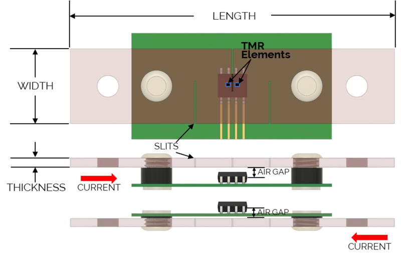
To optimize performance, the TMR sensor is placed on a busbar and its current sensing range is adjusted using the busbar’s cross-sectional dimensions of Length, Width, and Thickness, as well as the air gap distance between the sensor and busbar. The spacing distance between the TMR sensor and the busbar is defined as the ‘air gap’, minimizing the air gap will increase the sensing range but will also minimize the voltage isolation. The busbar has a slit cut for the purpose of routing the current and enabling a high CMFR as shown in Figure 5.
The sensor can be placed over or under the current carrying busbar and still yield a non-contact and isolated current measurement. Note the busbar top or bottom position relative to the IC will determine the measured current’s polarity (Figure 6).
Click image to enlarge
Figure 6: Busbar Positioning
Compared with the traditional shunt and Hall current sensors, the new TMR sensor has a higher SNR, better temperature stability, built in CMFR and can be packaged in a smaller area since no shielding is required. The sensed current range can be adjusted by busbar dimensions making it very suitable for a wide range of BMS current requirements in electric vehicles.
Electric vehicles are becoming the norm for electromobility, and their battery power density continues to increase to accommodate a longer driving range. As the EV battery’s maximum current continues to rise, precise measurements require a new sensor technology. Traditional current sensors cannot meet the needs for accurate current measurement, high sensitivity, high CMFR, low power and compact design. Crocus TMR sensors present an improved contactless current sense option for electric vehicle applications.