Some challenging applications require special wirewounds with conflicting requirements
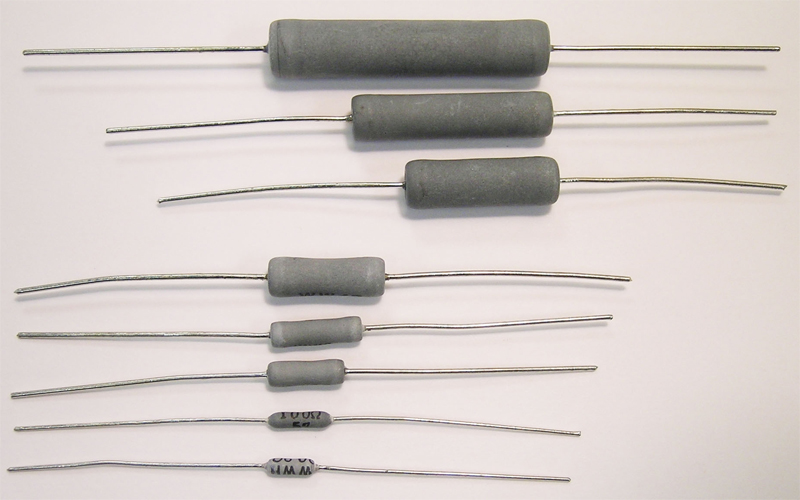
Figure 1: Devices like these handle thousands of 6KV surges yet fuse quickly under continuous overload
Wirewound resistors have attributes that give them advantages over film resistors. Frequently, engineers have designs that require a resistor to meet specific characteristics in order to satisfy the unique demands of their applications. These requirements range from inductance to power ratings to the usual requirement of minimizing cost. This article will cover the different resistor attributes that can be adjusted, as well as the effects that these changes may have on the part and its performance. It is critical for design engineers to understand the wide capability range of wirewound technology, as well as the unintended effects of making certain changes. Some of the most challenging applications, such as utility meters, require special wirewounds that have two conflicting requirements: 1) The need to withstand pulses with significant energy 2) The need to fuse quickly, safely, and without creating significant heat or sparks. Pulses and transients Utility meters typically are required to withstand a significant surge, usually between 6KV and 10KV. Wirewound resistors are used here in conjunction with a transient voltage suppression device such as an MOV. The wirewound resistor takes a portion of the surge energy so that the MOV doesn't have to bear the entire surge by itself. This means that the MOV can be sized significantly smaller and that it will be able to survive multiple surges with much less degradation (see Figure 1). For surviving the surge, a robust wirewound element is critical; film technology and solid composition resistors simply don't have the energy handling capacity or the accuracy and stability that wirewounds offer. However, in addition to surviving this difficult surge, this wirewound needs to fuse when subjected to a continuous 120VAC or 220VAC. This may happen if the meter is installed wrong. Under these conditions, the wirewound needs to open as quickly and with as little heat generated as possible. The two requirements together mean the wirewound solution must be a combination of wire alloy, size, and resistance, use of fusing enhancement coatings, and in some cases the use of a thermal isolation sub layer under the wire to prevent sections of the element from dissipating their heat energy into the ceramic core. Inductance Wirewound resistors are inherently inductive, since they are manufactured in the exact same way as wirewound inductors. The amount of inductance can vary widely from size to size and from value to value, but typically ranges from around 10nH to around 10μH. A frequent request with a wirewound resistor is for lower inductance, or for it to be "non-inductively" wound. To achieve a wirewound with lower inductance, manufacturers can typically move to a smaller wire size, which would have a higher resistivity. This would allow the manufacturer to reach the resistance value with fewer turns. One side effect of doing this is reduced pulse handling capability, due to lower resistance wire mass. For non-inductively wound product, manufacturers typically use an Ayrton-Perry winding. This method uses two elements wound in opposite directions on a single part, where both elements are essentially double the requested resistance value. This helps to cancel the magnetic fields and lowers the inductance to between 0.1nH to 1nH typically. It is important to know that even though this is called a non-inductive part, the part still has some inductance. In addition, since this process requires two precision winding operations, an Ayrton-Perry winding has a dramatically higher manufacturing cost of around 2X a standard winding. High power, high pulse power, or energy withstanding For higher power, pulse power and energy handling, manufacturers can increase the wire size to lower the resistivity of the wire. This can dramatically increase the wire mass available to dissipate the electrical energy of the device. There are two potential side effects from doing this; 1) Increased inductance, since there will be more wire turns to achieve a given resistance value 2) There may also be some concerns about high voltage handling. High voltage could arc between windings if they are spaced too closely together and there is a void present in the coating or molding. High Voltage Withstanding For high voltage withstanding wirewounds there are two options. The easiest and least expensive option is to decrease the wire size, thus raising the resistivity of the wire element. This allows manufacturers to wind fewer turns, creating wider spacing between windings, which minimizes the risk of internal arcing whether or not there is a void in the coating or molding around the part. This process also lowers the inductance of the part. However, this part may have a lower overall pulse power or pulse energy handling capability. Although these factors may or may not be relevant to a design, it is important to understand the tradeoffs associated with increasing the voltage handling of a wirewound resistor. For applications where high voltage handling is required and high pulse energy or power handling is also required, simply decreasing the wire diameter will not work. Part of the solution for these applications is to use element wire that is coated. In this way, the part is protected from arcing even if the windings are touching each other. However, coated wire is much more difficult to weld and incurs higher manufacturing costs, so the first method is usually preferred whenever possible.
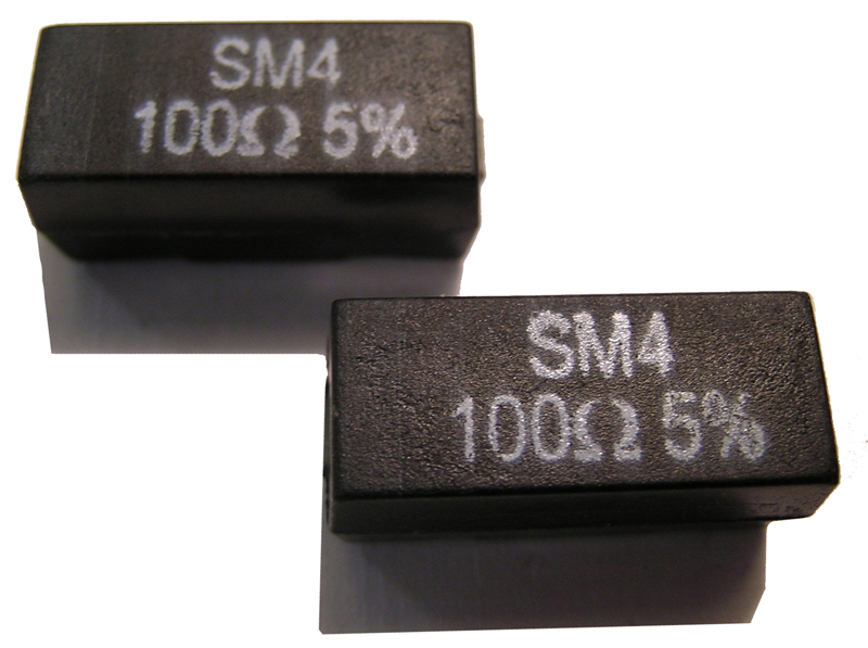
SMD Wirewounds Due to the continued demand for smaller and lighter electronics, new developments of SMD single layer varistors and SMD molded wirewounds have emerged (see Figure 2). A complete SMD protection solution using varistors and resistors is now possible. The SMD varistors use what is essentially a 5 mm or 7 mm single layer disk, which means that the current and energy handling range for this type of solution is still somewhat limited; however SMD molded wirewounds can now be found with power ratings of up to 5 watts, meaning that the price premium for these two SMD devices yields a solution that is comparatively very small, light, reliable, and uses the fewest amount of components. SMD single layer varistors have become more common, particularly with the development of SMD wirewounds rated higher than 3 watts. Fusing and Intrinsically Safe Failure One feature of wirewound technology is its robustness. This robustness can sometimes cause the part to overheat and potentially ignite itself, the PCB, and other components. Technological advancements have recently been made that enable the development of more sophisticated wirewound resistors that feature an extremely reliable and repeatable fusing characteristic. One method to achieve a fusing action is to use coating materials that concentrate the thermal energy and thus not allow this energy to be dissipated into the ambient air. Even under constant line overload, these parts fuse quickly and typically with low thermal stress to the PCB and surrounding components. However, this method does not reduce the part's ability to withstand short-term pulses, which is important to protect metering and monitoring equipment, as well as appliances such as washers, dryers and other white goods. Another method of creating a fusing characteristic is to decrease the wire size. The advantage to this method is that it still utilizes a straightforward manufacturing process and therefore less expensive than the first option. One limitation to this method is that the component will have lower short-term pulse handling capability. Stackpole


