Almost every electronic application incorporates DC-DC conversion in some form. Switched-mode topology is an efficient solution that enables step up and step down of DC voltage as well as isolation
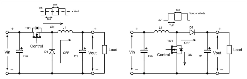
Figure 1: The buck and boost DC-DC converter outlines
This article gives a broad review of the switched-mode topology technology and some commercial implementations. Historically DC-DC conversion utilised a series pass element (transistor) with linear circuitry, resulting in woeful efficiency levels especially if the differential voltage across the series pass element is high, this results in poor efficiency with high thermal dissipation, requiring heatsink or forced air cooling, and taking valuable PCB real estate.
Switched-mode conversion solves the problem
The practical solution to efficient DC-DC conversion is the ‘switched-mode’ technique. When no isolation is required, ‘buck’ and ‘boost’ converters are used. The buck (Figure 1, left) produces an output voltage less than the input voltage, which is dependant on the switching duty cycle and input voltage. When the main Mosfet TR1 switch is closed the resulting current present in the inductor L1 creates a potential that is opposed to the input voltage, thereby creating a lower voltage, energy is stored both in the inductor and output capacitor and no current flows through the diode as it is reverse biased. Once the switch opens, the supply current to the inductor is interrupted, the diode now conducts providing a return path for the inductor current, this change causes a reverse voltage across the inductor, which then becomes the primary source of power during this phase. The boost converter (Figure 1, right) operates a little differently with TR1 off the output capacitor is charged as per the input voltage, when TR1 switches on, current charges up through L1, when TR1 switches back off, an opposing voltage is generated and released, the inductor now acts as a voltage source in series with the supply voltage, the output cap is now charged up to a higher voltage than before, therefore stepping up the voltage. Other circuit arrangements such as the simple buck-boost and Ćuk can produce voltage inversion, while the SEPIC, ZETA and others can produce positive output voltages lower or higher than the input.
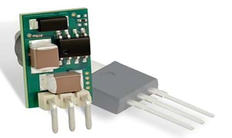
An example of Murata’s 78SR series [1] buck is shown in (Figure 2). The module has an input range of 7.5V to 36V for an output of 3.3V at 0.5A. At full load and 12V input, it achieves 83% efficiency, dissipating about 0.7W. It is pin-compatible with the popular ‘78xx’ series linear regulators which would dissipate a mighty 4.35W under the same conditions requiring mechanical heatsinking.
Click image to enlarge
Figure 2: Murata 78SR series buck converter rated at 0.5A
While this through-hole part can change out an existing linear regulator for a gain in efficiency, better performance still is achieved by surface mount ‘point-of-load’ (POL) DC-DC modules with land-grid array footprints. The MYMGA series from Murata for example achieves 94% efficiency at its full load current of 4A. This is all in a package of only 9mm x 10.5mm x 5.5mm high.
Click image to enlarge
Figure 3: MYMG Series
For higher power, ‘multiphase’ buck converters spread the component stresses across duplicated switches and inductors, driven in two or more phases with common input and output capacitors. For best efficiency, it is also possible to employ ‘synchronous rectification’ where the rectifier diode with its fixed voltage drop is replaced by a low on-resistance MOSFET, to gain even more efficiency.
Isolation is often required
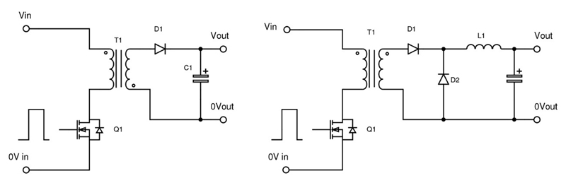
Simple buck and boost converters do not provide galvanic isolation – their input and output grounds are connected. For certain applications galvanic isolation is required, this could be because the input is referenced to an unsafe voltage (greater than the SELV limit of 60vDC), to prevent circulating ground currents, or simply so that the output can be configured as a negative voltage by grounding the positive. The equivalent isolated topologies to buck and boost are forward and flyback converters (Figure 4), which can be viewed as converting the inductor in each case into a transformer so an isolated winding can provide the DC output.
Click image to enlarge
Figure 4: Flyback (left) and forward (right) converter outlines
Isolated DC-DC converters are more difficult to fully regulate as the output voltage has to be sensed and an error signal passed back across the isolation barrier to the primary to control the duty cycle. Sometimes regulation is not necessary, for example if the DC input is stable and constant, only loading variations affect the output regulation, which might only change by a few percent, which can be acceptable.
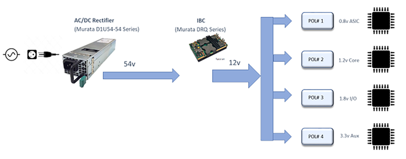
A key application technique today that requires little attention to the load/line regulation is deployed within datacom applications, by converting the high DC source voltage typically 48v DC derived from an AC front end or batteries to an isolated lower voltage which can be used for feeding into a non-isolated DC-DC converter result in large efficiency gains by reducing I2R losses within the application and improving the overall system efficiency than just using a single-stage DC-DC converter technique. This conversion stage uses an Intermediate Bus Converter (IBC) which is an isolated DC-DC converter with low regulation characteristics resulting in extremely high-efficiency levels up to 97%. The output voltage from the IBC is fed into a non-isolated Point of Load regulator (POL) that provides the end application usually silicon processors with very tight regulation and transient load characteristics.
Click image to enlarge
Figure 5: IBC Distributed Bus Architecture
When isolation is required for safety reasons, the spacings and insulation arrangements are complex. Creepage, clearance and distance through the isolation barrier depend on the level of protection required (basic, double or reinforced, for example) and other parameters such as environmental pollution degree, overvoltage category of the input and even altitude. The application sets the standards applied, for medical applications in a patient-connect environment for example, requiring larger separation distances than industrial. There can be confusion about stated isolation rating; parts are often promoted with say, 3kVDC test in production, which might seem adequate for isolation of 230Vac. However, this is only a one-off test voltage and does not guarantee that the part continuously withstands a high voltage. Users should look for an actual safety agency certification, the level tested to and the ‘system voltage’ it refers to.
Resonant converters are efficient
The forward converter appears in many varieties with different pros and cons, often dictated by the application trade-offs of efficiency, cost and size for given power and voltage conversion ratings. For optimum efficiency, ‘resonant’ converters are often used, which ‘soft switch’, that is, change switch state while current or voltage is zero. This avoids the momentary spike in power dissipation if the high voltage and high current occur together. A resonant technique such as “LLC” is used which applies pulses to an LC ‘tank’, typically just above its resonant frequency, with the pulses then passed as sine waves to a secondary load winding on the tank inductor, by transformer action. Regulation is achieved by varying the pulse frequency, which passes more or less energy through the transformer as a result of the increasing inductive impedance of the LC circuit with frequency, above resonance.
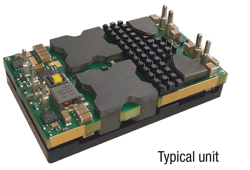
At high power, the stress on the LLC switching transistors becomes impractically high and then typically a ‘phase-shift full bridge’ topology is used. This is another resonant circuit in a four-switch bridge arrangement but operates at fixed frequency, with regulation achieved by varying the relative phase of the drive waveforms to each leg of the bridge. This technology is utilised in Intermediate Bus Converters such as the DRQ series from Murata.[5]
Click image to enlarge
Figure 6: Murata’s DRQ series of Intermediate Bus Converters.
Switched-capacitor DC-DC converters need no magnetics
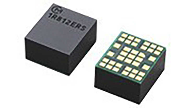
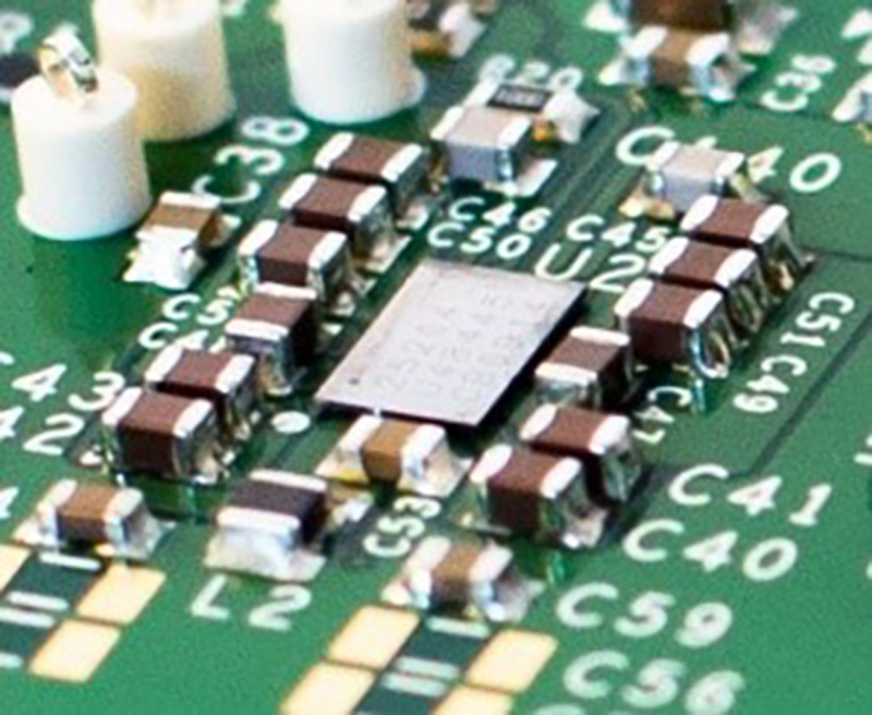
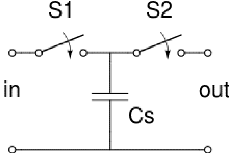
It is not necessary to use an inductor or transformer in a non-isolated DC-DC converter; switched capacitor arrangements can be used which charge capacitors in series or parallel then set them in parallel or series respectively to step down or up voltages respectively, in discrete multiples. Previously, switch and diode drops have limited the efficiency attainable but with modern MOSFETs and synchronous rectification, 96%+ can be achieved at 72W such as Murata’s Psemi novel switched capacitor technology Figure 7. There is typically no active regulation and the step up or down is in a fixed ratio, 3 or 4, this technique without an inductor lends itself to modern fabrication methods and low-profile products.
Click image to enlarge
Click image to enlarge
Figures 7a & 7b: Murata’s Psemi switched capacitor technology
Ultra-Wide DC Input Range Converters.
Having a single DC-DC converter that can operate from a multitude of battery voltages, can simplify applications where the manufacturer of the equipment is uncertain which voltage battery source will be used by the customer, for example, in railway applications, the battery can range from 24V up to 110V depending upon the manufacturer of the locomotive and the geographical region. Murata’s IRH250 / IRQ150 satisfy this challenge with a DC voltage input range of 16V – 160V DC, in a rugged baseplate cooled package

Click image to enlarge
Figure 8: Murata’s IRH250 ultra-wide DC Input range converters.
To conclude depending upon the application and its requirements determines the most efficient and optimised type of DC-DC converter required to fulfil the electrical, environmental, safety and physical requirements.