Lighting is one of the factors that greatly impacts human comfort
In this age of “green” building systems, it is incumbent upon commercial building owners and operators to reduce their day-to-day operating costs while at the same time ensuring the comfort of occupants. Lighting is one of the factors that greatly impacts human comfort. Too much or too little light can result in eyestrain and/or hamper productivity.
Intelligent lighting control systems allow building owners to create inviting and functional office environments that improve light quality, enhance efficiency and productivity, and optimize energy use. Think of it as a system that allows a building to make intelligent decisions about the optimum delivery of light. Lighting controls can switch lights off when no one is around, automatically adjust lighting levels based on the amount of natural daylight in the space and turn off or dim lights, based on the daily cycle of the office.
Digital Addressable Lighting Interface
One approach to an intelligent lighting control system is implemented through the Digital Addressable Lighting Interface (DALI). DALI is a protocol described in the technical standard IEC 62386 for digital control of building lighting systems. The interface is a simple two-wire affair with a maximum system size of 64 addresses. DALI stands separate from building-automation bus architectures but can be tied into those structures to pass along data regarding the status and condition of the lighting system.
Many standard interfaces, including DALI, are based on the fundamental building blocks of the Manchester or NRZ line-encoding schemes. As with any serial-data protocol, debugging depends on the ability of instruments such as digital oscilloscopes to properly decode the protocol. In this article, we’ll look at how this is accomplished by Teledyne LeCroy’s instruments through the use of a configurable Manchester decoder.
DALI Physical and Data Link Layers
Before examining the decoding of the specific signal as an example in this article, here are some basics on the DALI technical specification. More information on DALI is available at: dali-ag.org. Additionally, the DALI-interface has been described in the fluorescent lamp ballast standard IEC 60929 under Annex E.
At the physical layer, DALI uses an effective data transfer rate of 1.2 kb/s, enabling interference-free system operation. The physical low-level has been defined with the interface voltage at 0 V (-4.5 V to 4.5 V) on the receiver’s side. The high-level condition is represented by the interface voltage of 16 V (9.5 V to 22.5 V) on the receiving side. A maximum voltage drop of 2 V between sender and receiver is admissible on the leads of the interface.
There are two types of data frames in the DALI interface: forward frames and backward frames. Forward frames consist of 19 bits with timing and must have a duration in time of 38 Te, with Te, the duration in time of 1 bit at 1.2 kb/s being 416.67 µs.
Backward frames are sent only after the reception of a query command or a write memory command. A backward frame consists of 11 bits and must have a duration of 22 Te.
Embarking on a Decode
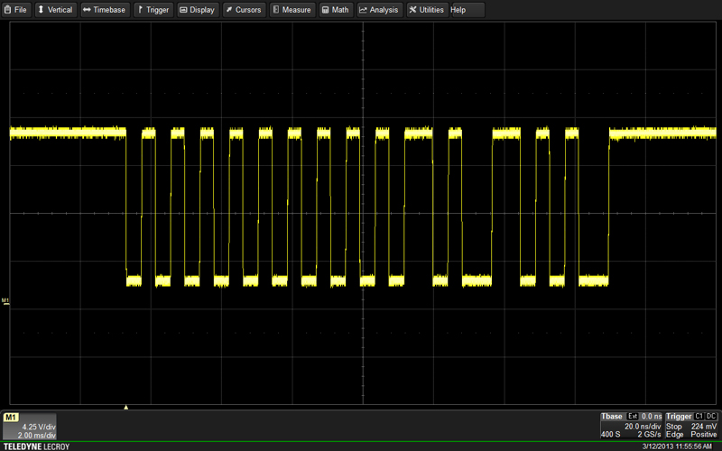
For this article, the signal at hand is a 1.2-kb/s DALI forward-frame signal consisting of two start bits (skipped), a 6-bit address, and one data bit as shown in Figure 1.
Click image to enlarge
Figure 1: A DALI signal with two start bits, a 6-bit address, and one data bit
Through the Analysis drop-down menu at the top of the oscilloscope’s screen, one accesses the Serial Decode dialog and from there, the Protocol menu. Selecting Manchester will activate the configurable Manchester protocol decoder.
The next step is to designate the source of the on-screen trace. For this article, the trace is stored in Memory 1 or M1. Although this example uses a memory trace, the decoder works on all channels and math, memory, and zoom traces. After assigning the on-screen trace to Decode 1 in the Serial Decode dialog box, pressing the Setup button opens the Decode Setup tab, where the oscilloscope is prepared for the Manchester decode.
Decode Setup: The Basic Tab
The Basic tab provides all of the fundamental controls required to allow proper bit-level decoding (names of settable parameters are shown in bold). The configurable Manchester decoder supports a wide range of bit rates. We know that the DALI physical specification dictates a fixed data rate of 1.2 kb/s, so the Bit Rate parameter in the Physical Layer portion of the Basic tab is set to that value.
The Timeout Definition for the gap between bursts comprises two parameters, Units and # Bits. The former can be set to either Bits or Seconds. If Bits is chosen, the range is from 1 to 100. If Seconds is used, the range is from 1 to 99.99 µs. The DALI specification dictates that for transmission of consecutive forward frames, the elapsed time between the end of the last stop bit and the beginning of the first start bit in the next forward frame must be at least 22 Te.
The Idle State, which complements the Timeout Definition parameter, may be set to either IdleHigh, IdleLow, or Don’t Care. Setting the Idle State parameter helps to define the separation gap between data bursts. In the case of DALI, the idle state is set to IdleHigh.
The Polarity may be set to either Falling = 0 or Falling = 1. This determines whether an edge falling through the threshold level is decoded as a logical 0 or a logical 1, respectively. The DALI specification dictates that an edge rising through the threshold is decoded as a logical 1. Thus, for this example, Polarity is set at Falling = 0.
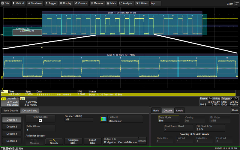
Next, we will look at the Decode tab. However, open a zoomed-in view of a portion of the decoded signal to ensure that the bit-level decode is correct (see Figure 2).
Click image to enlarge
Figure 2: Verifying correct bit-level decode with a zoomed view
Decode Setup: The Decode Tab
On the Decode tab, which is where decoding at the word level is set up, set the Data Mode to Bits. Note that in the zoomed view Z1, which corresponds to the highlighted portion in the center of M1, each binary 1 is represented by a negative half-bit period pulse followed by a positive half-bit period pulse. Similarly, a binary 0 is represented by a positive half-bit period pulse followed by a negative half-bit period pulse. This type of signaling is also called split-phase encoding. In this case, Polarity is set to physical Falling = 0.
The First Transition Used (FTU) parameter accounts for items that may precede the actual data payload. These might include such elements as a preamble or a synchronization sequence. The default setting for FTU is zero; it can range in increments of one to a maximum of 400.
The Bit Stretch Tolerance parameter comes into play when transitions often occur at mid-bit. Due to hardware or signal-propagation issues, these mid-bits may not be perfectly equidistant. This parameter is adjusted to better decode jittery signals. After setting the Bit Rate on the Basic tab, the Bit Stretch Tolerance may require adjustment from its default setting of 20% to achieve stable decoding.
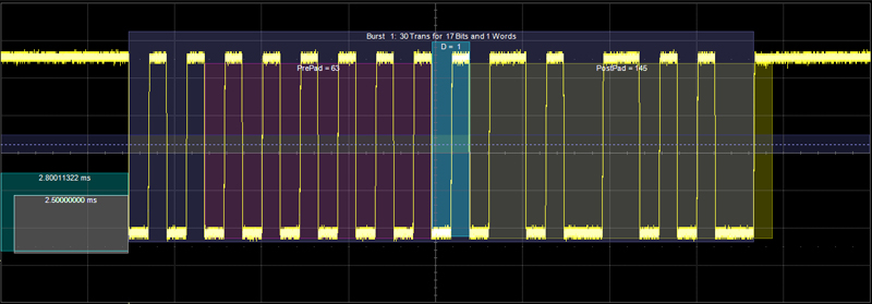
At the bottom of the Decode tab is a number of parameters for Grouping of Bits into Words. Figure 3 shows the DALI signal grouped into words. It is important here to ensure that the Data Mode is set to Words.
Click image to enlarge
Figure 3: A Manchester signal shown decoded in Word Mode
Within the Manchester decode software are tools and capabilities to group bits into Sync Bits, PrePad, Data Bits, and PostPad. Again, the DALI forward frame signal consists of one start bit, one address byte, one data byte, and two stop bits (idle line).
PrePad bits in a DALI frame would include the start bits and address. In Figure 3, they are the portions of the bit stream seen with a purple overlay. With the start bits skipped in this example, the PrePad bits are the six address bits in this example. As noted above, the Y and S bits shown in Figure 1 are omitted.
The Manchester decoder can parse from 1 to 32 Data bits. The DALI specification calls for one data byte. The trace used for this document uses a single Data bit for the Selector bit. The selector bit is set at a logical one, indicating that the data payload will contain a command. The Data Bits appear with a blue overlay.
Typically, PostPad bits numbering from zero to 32 serve to group information following the data bits. PostPad bits can represent a CRC, a checksum, or other protocol constructs. In the example shown in this document, the PostPad bits are used for the actual data payload of the frame. Within the data is the value 145, which in the DALI protocol represents a command to Query Control Gear. Because they are idle-line bits, the Stop bits are omitted. PostPad bits appear with a yellow overlay.
Decode Setup: The Level Tab
The last of the three tabs in the Decode Setup dialog box is the Level tab. Levels can be set using either percentage or absolute voltage values as determined by the Level Type setting. The Level setting itself determines the threshold that transitions must cross to be counted as transitions. The default value is 50% or 1.5 V for percentage and absolute level types, respectively.
Hysteresis settings account for noisy signals with spikes that may create false transitions if they cross the Level threshold. It appears as a blue-shaded band centered vertically on the Level setting. The default Hysteresis value is 15% but can vary from zero to 50%.
Conclusion
For designers and/or integrators of DALI-based intelligent lighting systems in commercial buildings, the protocol provides a means to reducing operating costs and delivering a work environment that is aesthetically pleasing as well as comfortable. An oscilloscope equipped with a configurable Manchester protocol decoder can be an invaluable tool in debugging the DALI protocol, as well as other protocols encoded with the Manchester scheme. Armed with a bit of foreknowledge of the signal under test, users may exploit the decoder’s nearly unlimited flexibility with respect to signal parameters to cleanly decode and display signals and extract data relative to their physical characteristics.