Delivering a Complete Active Power Factor Correction Solution in a Single Package: Part 2 of 4

HiperPFS-4 with Integrated 600 V Qspeed Diode Application
Two of the main issues for modern power supply designers are the elimination of unwanted line harmonic currents and ensuring a power factor that is as close to unity as possible. Unwanted harmonics can cause transmission equipment to overheat and pose interference challenges that must be addressed later; both also have an adverse effect on the size and/or efficiency of the circuit. If the load applied to the line is not purely resistive, a phase shift will be induced between line voltage and current waveforms, increasing apparent power and reducing transmission efficiency. If a non-linear load distorts the input current waveform, then current harmonics will be induced that further reduce transmission efficiency and introduce interference into the mains network.
Finding solutions to these problems requires a knowledge of the fundamentals of power conversion. In a power supply, a normal AC voltage source (e.g., a wall outlet) is initially connected to a rectifier. The rectifier converts the AC voltage into a fixed-polarity representation of the AC signal and a peak voltage equivalent to VDC. This signal is fed into a bulk capacitor, which acts like a filter to smooth out the ripple in the voltage waveform. The newly created DC signal is fed through to the DC/DC converter stage of the power supply to achieve the low-voltage DC required for the final output.
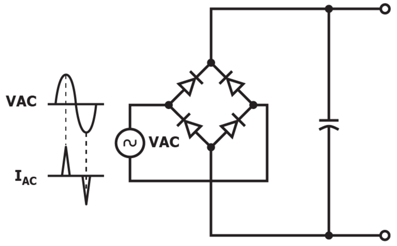
If we return to the original rectification stage and look at the waveforms, the input AC voltage is a traditional symmetrical sine wave with alternating positive and negative polarity. However, the input current appears as a series of spikes that increase in size as the input voltage rises. This is because diode conduction (and therefore current flow) will only occur when the bulk capacitor is being charged – when the VAC line voltage exceeds the DC voltage stored on the capacitor. The charge stored on the bulk capacitor will support the output of the power supply when the VAC falls below the stored capacitor voltage. The transfer of energy from the capacitor to the load during this time causes the voltage on the capacitor to fall. The capacitor is re-charged once the AC voltage again exceeds the (now lower) voltage on the reservoir capacitor. This short charging window means that input current is delivered as a triangular pulse rather than as a sinusoid.
Click image to enlarge
Figure 1: The input current at the rectification stage appears as a series of spikes that contain a lot of harmonic content, polluting the AC line
This type of spiked current waveform is made up of a series of harmonics of the line frequency. The harmonic content is limited by various national and international regulations that have been put in place to protect the distribution network. A circuit like the one shown in Figure 1 will tend to have a power factor that is quite low, at around 0.5, which is a long way from the ideal figure of 1.
This issue can be addressed in several different ways. The simplest method is to add an inductor to cancel out the capacitive component of the circuit – a technique called passive power factor correction. However, passive power correction is of limited use. In applications that have a high-power output, the physical size of the required inductor makes it impractical. In such cases, an active PFC circuit is typically used to get the power factor of the circuit closer to unity without negatively affecting the size of the circuit. Active power factor correction uses a PFC diode, an inductor and a MOSFET. The MOSFET acts as a high-frequency switch driven by a controller executing a power factor correction algorithm.
The switching circuit forces the input current to follow the rectified VAC input and becomes a proper sine wave again. The sine wave ideally has low distortion, eliminating the harmonic currents that pollute the AC line. Because the voltage and current waveforms are in phase, the power factor also rises close to the ideal figure of 1.

Click image to enlarge
Figure 2: The rectification stage with active power factor correction to change the input current to a sine wave
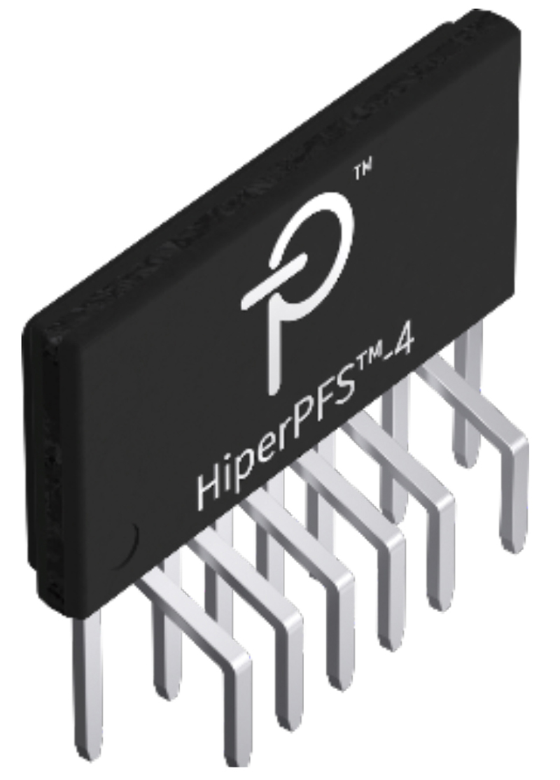
A simple way to implement an active PFC circuit is to use Power Integrations’ HiperPFS-4 solution (Figure 3). The HiperPFS-4 device includes an ultra-low reverse recovery charge diode that achieves high efficiency by minimizing diode transition losses. It also features a low RDS(ON) MOSFET that reduces conduction losses and an advanced continuous conduction mode controller that integrates many safety features.
Click image to enlarge
Figure 3: HiperPFS-4 from Power Integrations
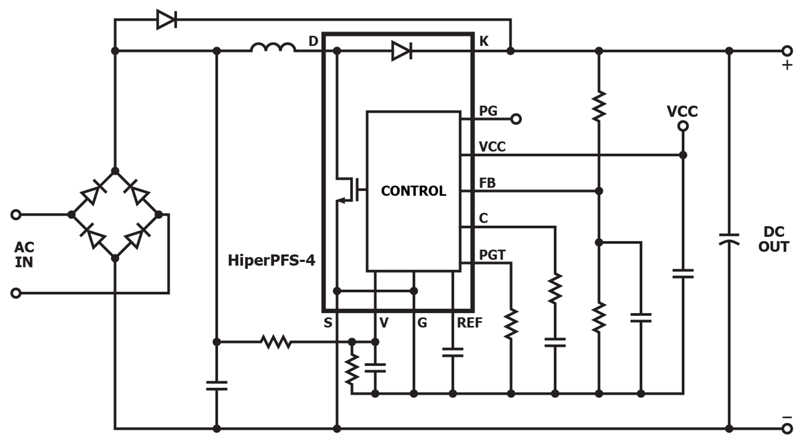
The integration of the power factor correction diode, MOSFET and controller in the HiperPFS-4 device provides a high level of integration, decreasing development time and allowing quicker time to market. Another advantage of integrating the critical components in a single package is the minimization of parasitic inductances in the interconnections. The reduction of circuit inductance increases the reliability of the circuit by reducing the voltage stress both across the PFC diode and the peak drain-source voltage of the MOSFET. In addition, the diode used has soft recovery reducing ringing, and therefore EMI. Integrating the diode and MOSFET in a single package provides a significant reduction in loop size, further reducing EMI.
Click image to enlarge
Figure 4: The HiperPFS-4 device includes critical components for active power factor correction in a single package to minimize parasitic inductances in the interconnections, which reduces di/dt induced voltage stress across the power switch
Summary
Active power factor correction is the best method of reducing unwanted line harmonic currents and increasing the power factor. Power Integrations has developed the HiperPFS-4 solution to integrate key components required for active power factor correction into a single package. This arrangement drastically cuts line current harmonics and increases the power factor, while addressing many of the layout problems that can be found in conventional implementations of this circuit, such as reducing voltage stress, EMI and parasitic losses.
For more details on HiperPFS-4 ICs, please visit the Power Integrations website at power.com.