Designing a DiSEqC-antenna phantom power-supply
A simple phantom power supply design allows power, a control link, and the received radio signal to coexist on the coax
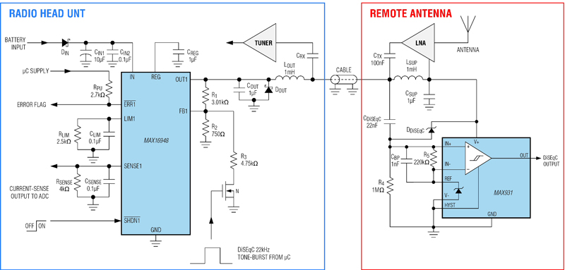
Figure 1: The DiSEqC application circuit
The DiSEqC (digital satellite equipment control) standard is a communication protocol developed by Eutelsat used between a satellite receiver (decoder), defined as the master, and satellite peripheral equipment such as dish switchers, LNBs (low-noise blocks), and dish positioners, defined as slaves. The DiSEqC communication system uses only the existing coaxial cable, thus making DiSEqC well suited to reduce cost and improve reliability. The DiSEqC is an open standard with nonproprietary commands. To allow one-way DiSEqC communication on the antenna cable, the radio head unit must transmit a 22-kHz tone burst, which the remote antenna must receive. The voltage amplitude of this tone burst is 650 mV, as the DiSEqC standard requires. Note that the antenna coax cable also feeds the LNA (low-noise amplifier) and carries the received radio signal. For this reason, the DiSEqC receiver must be able to reject the radio signal on the cable. Application Circuit In a DiSEqC application circuit, a dual high-voltage, current-sense LDO/switch is used in LDO mode and the regulated output voltage is dynamically changed to generate the DiSEqC pulses (figure 1). The blue block is the radio head unit, which includes the remote antenna power supply used also as DiSEqC tone-burst transmitter and the tuner. The red block is the remote antenna formed by the physical antenna, the LNA, and the DiSEqC receiver (a low-power comparator, such as a MAX9311). The coax cable enables the communication between the radio head unit and the remote antenna (radio signal and DiSEqC tone-burst) and is also used to feed the remote LNA, saving cost and cable weight. The automotive LDO/switch is configured in LDO mode with a 5-V voltage output when the external NMOS is turned off (DiSEqC tone-burst off). Choosing resistors R1 and R2 determines this output voltage, as indicated in the device's data sheet (reference 1) and related application note (reference 2). If a different remote antenna feed voltage (VOUT) is required, use the following equation to choose R1 based on R2:
where V:FB is the voltage at the feedback pin in regulation (1 V, nominal) and R2 must be less than or equal to 1 k?. When the external NMOS turns on, resistor R3 connects in parallel with R2. This brings the LDO regulator output voltage to 5.65 V. With this circuit configuration, a user can easily generate a DiSEqC 22-kHz tone burst by turning the external NMOS on and off through the microcontroller. If a different remote-antenna feed voltage is required, choose a value for resistor R3 using the equation
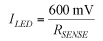
RLIM and RSENSE set the output current limit to 200 mA and the ADC full-scale range to 4 V (reference 3). For reasons of clarity, only one channel of the LDO/switch appears on the schematic, but the same considerations are valid for the second channel.
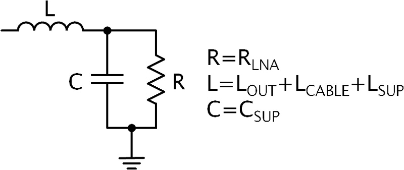
The output inductor, LOUT, is necessary to filter out the radio signal and to not conflict with the LDO regulator. Considering the AM band's lower frequency of 148 kHz, a 1-mH output inductor is sufficient. The tuner extracts the radio signal from the coax cable with a bypass capacitor, CRX. The remote antenna power supply used to feed the LNA is obtained through a lowpass filter built with inductor, LSUP, and capacitor, CSUP. To a first approximation, the power-supply filter is an RLC lowpass filter (figure 2). The -3dB passband must be below the frequency used for DiSEqC communication.
The low-power comparator acts as the DiSEqC receiver and is supplied with the same voltage supply as the LNA. The negative comparator input, IN-, is connected to the REF voltage provided by the comparator itself, while the positive comparator input, IN+, is polarized with a resistor divider, R4 and R5, in order to have zero voltage output on the DiSEqC output in the absence of a DiSEqC tone-burst.
To sense the DiSEqC tone-burst, a 22-nF capacitor, CDiSEqC, connects between the coax cable and the negative comparator input. When a tone-burst is sent on the coax cable, the IN+ voltage exceeds the IN- voltage, which generates a pulse on the output of the comparator. A protection Schottky diode, DDiSEqC connects between IN+ and the comparator power supply input, V+, to avoid an over-voltage fault on the IN+ pin.
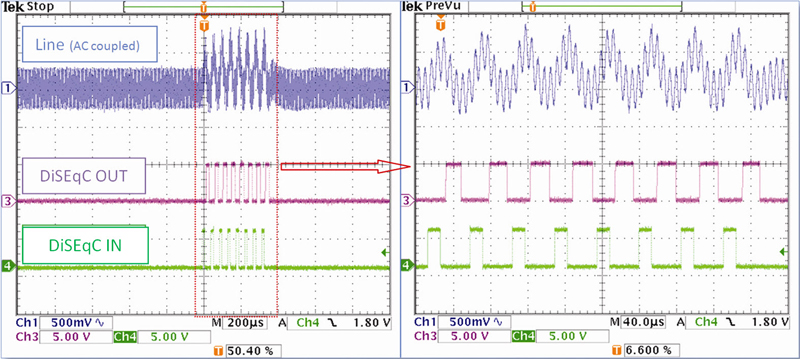
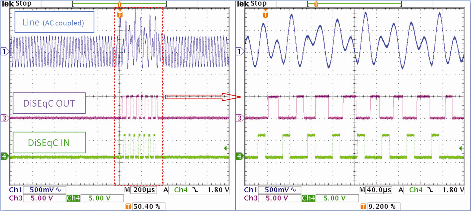
To avoid false output pulse triggering due to the radio signal travelling on the cable, a 1-nF bypass capacitor, CBP, is placed between the comparator inputs, from IN+ to IN-. The radio signal received from the remote antenna and amplified with the LNA is injected onto the cable with a capacitor CTX Bench tests were performed, which generated eight 5-V-amplitude 22-kHz tone-bursts with a waveform generator connected to the gate of the external NMOS. A sinusoidal 500-mV amplitude RF signal was obtained with another waveform generator and injected with the CTX capacitor, emulating the LNA output radio signal. An oscilloscope monitored the output of the comparator to confirm whether the sent tone-bursts were received and to ensure that the injected radio signal did not influence the DiSEqC communication.
Figure 3 and Figure 4 illustrate the scope traces corresponding to the performed tests. Figure 3 shows the results with an injected radio signal at 148 kHz and 500-mV amplitude, which coincides with the lower AM band frequency. Figure 4 shows the results with an injected radio signal at 37 kHz and 500-mV amplitude, which is the second subharmonic of the lower AM band frequency, 148 kHz,.
The DiSEqC application circuit is a low-cost and flexible design for an antenna phantom power supply that is compatible with the DiSEqC communication standard. Additional bench test results have confirmed that DiSEqC communication still operates when selecting the DiSEqC tone-burst frequency in the range between 100 Hz and 30 kHz. This provides the flexibility to tune the most suitable frequency for DiSEqC communication, thus minimizing interference with other RF signals on the coax cable. Product designers can also regulate the tone-burst duty cycle and add hysteresis to the comparator to attain the best DiSEqC communication performance. This application circuit enables one-way DiSEqC communication. If a receive-acknowledge signal is needed from the remote antenna, it can be generated by modulating the load current of the LDO/switch. A simple way to do this would be to connect an extra load in parallel to the LNA supply inside the remote antenna once the DiSEqC message is received. The microcontroller in the radio head unit can receive the acknowledgment by sampling the load current variation on the MAX16948's current-sense output, SENSE. The switched extra load could be easily built up with an NMOS switch in series with a pullup resistor connected to the LNA supply inside the remote antenna. References 1. MAX16948 data sheet: www.maximintegrated.com/MAX16948 2. Maxim application note 5271, Selecting External Components for an Automotive Dual Remote Antenna Current-Sense LDO/Switch, www.maximintegrated.com/AN5271. Maxim Integrated


