Within this standard, there are three categories of equipment
Power supplies for medical equipment must comply with IEC/UL 60601-1 3rd edition. Within this standard there are three categories of equipment. B-rated equipment will have only brief contact with a patient – for example an MRI scanner. BF-rated equipment will have routine contact with the skin; for example ultrasound equipment. CF-rated equipment is likely to make direct internal contact with a patient, for example surgical cauterizers, cameras, and measurement devices.
All three categories pose special challenges for the power supply designer, with the CF-Rated category being the most difficult. These challenges fall into four main areas.
1. Creepage Distance and Air Clearance
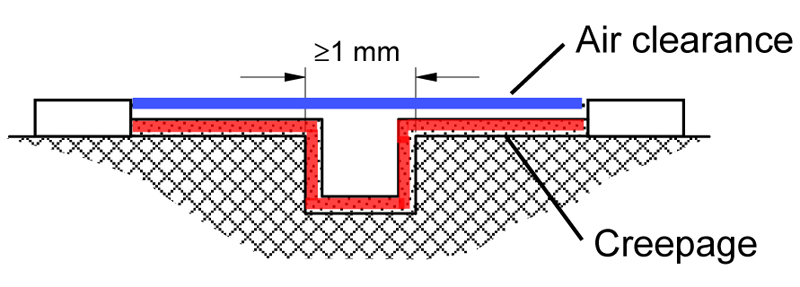
To block stray currents that can harm patients, medical PSUs require greater isolation between the primary and secondary than do industrial or consumer PSUs. This applies to both creepage distance (the shortest path along an insulating surface like the PC board) and air clearance (the shortest path through air). See Figure 1.
Per UL 60601-1, a universal input (90-264 VAC) medical PSU requires 8 mm creepage and 4.5 mm clearance – about 25% greater than the 6.3 mm creepage and 3.0 mm clearance for an industrial PSU designed to UL60950-1. These limits apply to the transformer, to the optocoupler, and to the separation between the primary side and secondary side of components on printed circuit board.
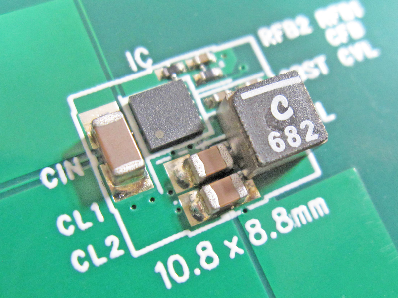
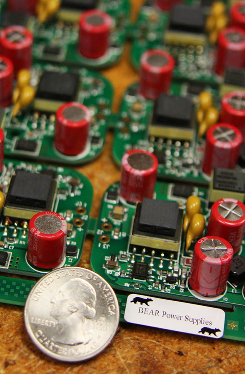
For very small power supplies, it can be extremely challenging to meet the requirements and achieve the small form factor that is required for portable medical devices.
Sometimes the only solution is to encapsulate the board in epoxy. A UL-approved encapsulation system can reduce the 8 mm creepage requirement to just 1 mm. See Figure 2.
Click image to enlarge
Figure 2 – This medical power supply needs to fit in a very small enclosure, making it impossible to separate the components for sufficient creepage distance and air clearance. Encapsulating the board in epoxy allows us to meet these requirements.
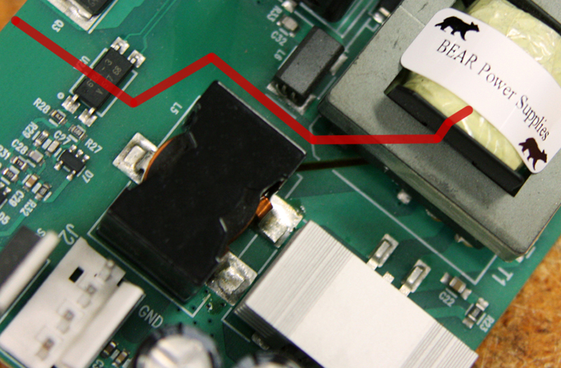
Another technique is to add a slot to the printed circuit board. By breaking the path along the board, it essentially converts a path of creepage (which would need to be 8 mm) to a path of clearance (which requires only 4.5 mm). See Figure 3.
Click image to enlarge
Figure 3 – The line shows the approximate isolation barrier between the primary components (top) and secondary components (bottom). There was insufficient creepage between the two. Adding a slot in the PCB converts the creepage path to a clearance path, and reduces the distance needed from 8 mm to 4.5 mm.
An optocoupler is needed for feedback on a power supply. However, most off-the-shelf optocouplers are geared for industrial power supplies and don’t meet the creepage requirement for medical. Those that can meet the requirement are of course more costly. Alternatively, you can encase the optocoupler in epoxy. This also adds to the cost of the power supply.
Finally, you need to design and build a transformer. When you begin, you will find that many standard bobbins do not meet the 8mm creepage from the pin to winding window. You will have to either add margin tape, or use triple-insulated wire.
Margin tape takes up space on the winding window, resulting in fewer turns per layer. The transformer will require more tape material and more time to put it on, both of which add to the cost.
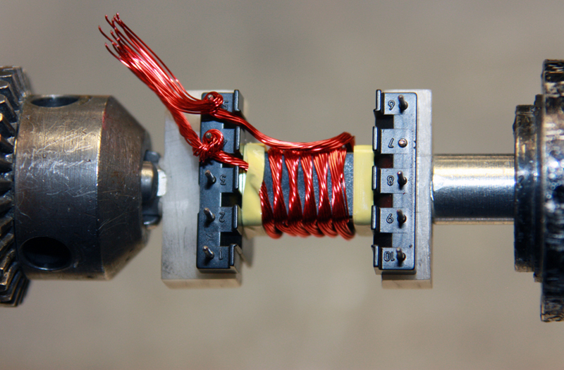
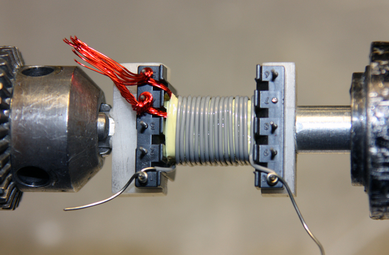
Click images to enlarge
Figure 4 – Coil winding for a transformer. Top: margin tape narrows the available winding window. Bottom: Triple-insulated wire adds bulk.
Triple-insulated wire also takes up space in the winding window. The triple insulation almost doubles the diameter of 30AWG wire, from 0.012” diameter to 0.022” diameter. It is also thirty times as expensive; about $0.095/foot for 30AWG single-strand triple-insulated wire compared to $0.003/foot for magnetic wire. If you use Litz wire (individually-insulated magnetic wires twisted or braided together) to reduce AC losses in high frequency windings, the cost is even higher.
Both margin tape and insulated wire mean fewer turns per layer, increasing the chance that you will need multiple layers of winding. This increases your magnetic size and/or decreases your coupling/leakage inductance, reducing power supply efficiency.
Access to coil-winding production equipment is a great advantage when designing a transformer. Design engineers can wind the first few transformers themselves, looking atmanufacturability while keeping in mind the overall product and design restraints. It is much easier to tweak the initial transformer designs to meet the power supply’s unique requirements when you have these capabilities in-house. Otherwise you need to find a specialty magnetic design house that can turn your prototypes around quickly, and you can expect to pay well for it.
2. Leakage Current (primary to secondary)
Medical rated PSUs require very low patient leakage current, that is, the current from the AC line to the patient (secondary). This complicates the transformer design, especially with CF-Rated supplies.
For CF-Rated supplies the leakage current limit is 10µA and 50µA for single fault conditions, which results in a 100 pF limit on the capacitance.
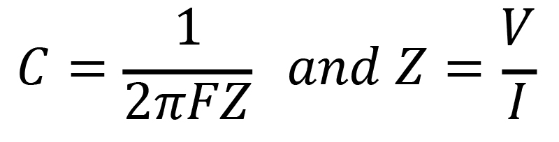
Where, C=capacitance (F), V=Voltage (RMS at high line (264VAC)), I= current=10µA, F=Frequency (60Hz)
In a typical industrial power supply, this 100 pF limit is exceeded by the transformer inter-winding capacitance alone.
For B- and BF-Rated medical power supplies the limit is 100µA and 500µA for single fault conditions, which results in a 1nF limit on the capacitance.
This means you can’t have a large Y-capacitor across the isolation barrier between primary ground and secondary ground. In a typical, offline switching power supply we would use a Y-capacitor of 1nF to 4.7nF to improve conducted and radiated emissions This is too large for medical power supplies. Not using a Y-capacitor will typically increase our conducted and radiated emissions (EMI) by 10-20dB or more.
One solution to help improve EMI is to add shields between primary and secondary. This adds cost to the build and more build on the transformer, which can result in a larger transformer.
If you add shielding and still do not quite achieve the EMI specifications, you may find that adding a SMALL Y-capacitor between the primary and secondary creates the “magic fix.” In this case, keep in mind that the new 3rd edition of 60601-1 now requires two Y1-rated capacitors in series. Again this adds cost and size. See Figure 5.
Click image to enlarge
Figure 5 - Two small Y-caps (orange) between the primary and secondary help meet EMI specs.
3. Dielectric Strength
The dielectric strength between primary and secondary for universal input power supplies is 4000 VAC for medical power supplies, compared to 3000 VAC for industrial and consumer models.
The two solutions to achieve this high dielectric strength are triple-insulated wire or tape rated for this higher voltage. Both solutions are of course more expensive. Less expensive tape can be used, but the need to use more layers will offset any savings.
4. Strict EMI Requirements
Medical power supplies must meet UL/IEC61000-1 standard Class A for hospital environments and Class B for medical office or in-home health care environments.
With the strict requirements on the transformer and the lack of a large Y-capacitor, the power supply designer will have to use other EMI reduction measures.
One technique is to add snubbers and ferrite beads around every switching node (input MOSFETs and output MOSFETs and diodes). Alternatively, you can create more complex filters on the input of the power supply. Again, both options add to the cost and size of the product.
Conclusion
Meeting the challenges of UL 60601-1 3rd edition involves more complex isolation techniques, requiring that are larger and more expensive components than those used in industrial or commercial power supplies. Experienced power supply designers can design these transformers and other components to maximize performance and reliability, and keep costs within reason, while meeting the justifiably stringent requirements that ensure patient safety.
Bear Power Supplies