The latest ratification of IEEE 802.3bt for Power over Ethernet opens the market for more power-hungry devices, opening the doors to more applications
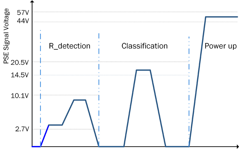
Figure 1: Waveforms during Startup Phase
Internet-connected devices rely on two core features, communications backhaul and power. With IoT devices, three core concerns regularly crop up: power, communications and security. Wireless technologies, like WiFi, have held the spotlight in the marketplace for years, but they struggle with these three problems. Wireless battery-operated devices need regular charging and WiFi suffers from saturation in its frequency bands; both common concerns today. Larger power requirements necessitate mains connections, which complicates and limits installation points.
Power over Ethernet (PoE) tackles these issues by offering flexibility, reliability, security and power over existing Ethernet infrastructure. It has grown in leaps and bounds since its initial release by the IEEE in 2003. The latest ratification to IEEE 802.3bt makes it a serious market competitor, offering 10G-BASE-T and 60 W to 90 W of power over Cat5/Cat6 cable.
Increased power
Initially, Type 1 Power Sourcing Equipment (or PSE) could only provide up to 15.4 W, Type 2 doubled that to 30 W. Now Type 3 and Type 4, released in September 2018, are taking that to 60 W and 90 W respectively. This opens the doors to a world of internet-enabled devices, including wireless and cellular base stations, Pan-Tilt-Zoom (PZT) and dome cameras, televisions, interactive displays and information kiosks. The single low voltage cable simultaneously coupled with dedicated high-speed communications means less wiring, ideal for smart building maintenance and installation for both the Internet of Things (IoT) and the Industrial Internet of Things (IIoT).
Power over Ethernet is a wired communications and power delivery system that uses existing Ethernet networks to power endpoint devices. In these systems, the Power Sourcing Equipment (PSE,) provides power over eight wires arranged as four twisted pairs (Cat5/Cat5e/Cat6/Cat6a) cabling with RJ45 style connectors to the connected Powered Devices (PD). The PSE provides a voltage up to 57 V to the endpoint. As this is less than 60 V, it meets the Safety Extra Low Voltage directive (SELV) making it electrically safe and negates the need for a qualified electrician or burying the cable, simplifying installation and maintenance. The standard limits the power per port to 90W, making this the maximum power transmitted over Ethernet cables.
Initially targeted for release in 2017, the standard was updated continuously before the official release in order to ensure backwards-compatibility with previous revisions. The latest update to the PoE specification, IEEE 802.3bt, introduces Type 3 and Type 4 Power Sourcing Equipment (PSE) and Powered Devices (PD). In order to supply higher currents, the new standard allows the two Power Modes (Mode A and Mode B) to be used simultaneously, commonly known as 4-pair or 4PPOE, supplies power over the 4-pairs instead of two as in Type 1 and 2.
Click image to enlarge
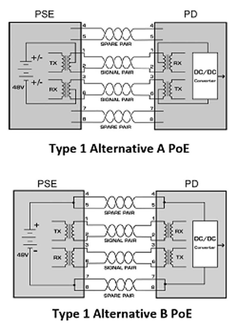
Figure 2: Mode A and Mode B PoE Power Delivery
Three additional classes, 5 to 8 have been added with an improved mutual identification process and automatic class functionality. This update also brings lower standby power and support for 10G-BASE-T alongside PoE.
Click image to enlarge
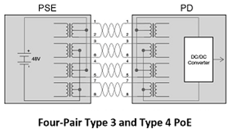
Figure 3: 4-Pair PoE Power Delivery
Designing with PoE
When designing the Powered Devices, there are a number of features to be considered, including mode of operation, PD detection and classification. In order to avoid damage to non-PoE devices, the PSE must detect if a powered device has been connected before providing power. The PD mode is detected using a valid signature, and implemented using a 25 kΩ resistor in the Powered Device. When the PSE provides two consecutive voltages (V1 = 2.7 V and V2 = 10.1 V) for resistance detection, it records the current values, establishing the presence of a PD, before activating the power to the device. Figure 1 depicts the resistor detection phase during startup.
In the classification stage, the maximum power requirements of the Powered Device are identified. Another resistor, attached to the PoE controller in the PD, indicates the power range. Class is not to be confused with Type as it refers to the specific amount of power for the attached device. In IEEE 802.3af/at (Type 1 and Type 2 devices) a single-signature PD is used. IEEE 802.3bt adds dual-signature PDs, where separate input bridge rectifiers and PD controller are used for each mode or alternative (A and B).
An optional extension of the classification is Autoclass. In Autoclass, the PSE measures the power consumption of the connected PD over a specific period of time, allowing the PSE to determine the maximum power the PD will ever require. Autoclass is never implemented with dual-signature PDs.
Once the Powered Device has been detected and the class has been determined, it must maintain the power signature. For Type 1 and Type 2 devices, the minimum power signature required was 10mA with a duty cycle of 20%. In order to keep the port alive, an average current of at least 2.31 mA was wasted. This works out as 115 mW at 50 V, which adds up very quickly with larger deployments. For Type 3 and Type 4 Powered Devices, the duty cycle was reduced to 1.875 %, which results in less than 10 mW per device, making a 90% reduction in standby power.
MPS is strictly required in connected lighting applications, where a large number of devices exist on a network. It is also required, even if less critical, for always-on devices like wireless backhaul, Wi-Fi access points and security cameras.
PoE Modes
Power delivery is split between three modes: Mode A, Mode B (also known as Alternative A and Alternative B) and 4-Pair. In case of 10BASE-T/100BASE-TX, In Mode A the power is delivered simultaneously with the data pairs 1-2 and 3-6. Mode B delivers powers over the spare pairs 4-5 and 7-8. In 1000BASE-T applications (four pair), also in both Mode-A and Mode-B power is delivered simultaneously on 4-Pairs. The common-mode voltage is extracted using the center tap of a standard Ethernet transformer, then, a DC/DC converter provides a regulated output voltage to the system.
In designing devices using PoE, it is important to consider the interconnecting cable. The maximum cable length for Ethernet is 100 m, which presents a DC resistance, simultaneously dropping voltage and dissipating power through heat. Category 5 or Cat5 cable is a twisted pair cable used in Ethernet networking and is used to deliver power in PoE networks. It supports up to 100 Mhz, suitable for 10/100/1000BASE-T. Category 6 or Cat6 is an improvement on the Cat5 cabling and supports up to 500 Mhz suitable for 10GBASE-T Ethernet speeds.
A 100m Cat5 cable has a DC resistance of 12.5 Ω, where the Cat6 cables exhibits a DC resistance of 7Ω per 100m. Transmission losses increase as the current in the differential pairs increase. With a typical input voltage of 50 V in a 25 W PD, the current is 0.5 A. This adds up to a transmission loss of 2.5 W in Cat5 and 1.75 W in Cat6, which is dissipated as heat. For a 90 W device, this transmission loss is shared across four pairs at 930 mA per pair, with a minimum of 52 V at the PSE. This works out as 17.30 W in Cat5 and 2x6.05 W in Cat6. This demonstrates that Cat5 is sufficientand safe enough for any application.
Getting connected
Cabling should be considered carefully in installations. A trade-off between cable length and power to the device must be calculated to increase efficiency and risk of damage to the cabling.
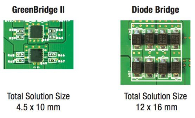
The Powered Device controller converts and, with an additional DC/DC Converter, regulates the input voltage at PD side. Diode bridges are a low-cost solution for typical PoE devices. These were sufficient on lower power devices, but as the power increases, this solution becomes problematic. With a 25.5 W and minimum 42.5 V, an estimated current of 0.6 A flows through the diode bridge. With a forward voltage of 0.7 V per diode, the power dissipated in each diode is 420 mW. For a 90 W system, the current is now 3.7 A with the power dissipated in each diode as 2.59 W.
Click image to enlarge
Figure 4: GreenBridge Solution versus Diode Bridge
A MOSFET approach improves conduction losses and efficiency over the conventional diode bridge. The first generation of the GreenBridge family of integrated dual P-channel and dual N-channel MOSFETS (FDMQ8203) from ON Semiconductor provide a neat solution to this problem in a compact and thermally enhanced surface mount package. The conduction loss is related to the RDS(ON) value of the MOSFETs. With an RDS(ON) of 110 mΩ and 190 mΩ for the N-channel and P-channel MOSFETS respectively the dissipated power can be calculated as 115 mW for a 25 W system. This is a quarter of the power of the diode bridge. In the 90W example, 3.7 A works out as 354 mW conduction loss, down to 13% of the diode solution. This may seem like a relatively small saving, but in a building management system, where hundreds of PoE sensors are used, the difference can be significant.
Click image to enlarge
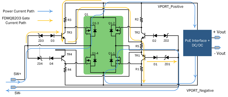
Figure 5: GreenBridge FDMQ8203 Quad MOSFET solution
The second generation Quad MOSFET solutions (FDMQ8025A) provide higher power rating, high efficiency bridge rectifiers as well as the necessary gate drivers, in the same small MPL 4.5 x 5mm package as the first generation and a much lower RDS(ON) of 35 mΩ for the N-channel MOSFETS and 76 mΩ for the P-channel MOSFETs.
On Semiconductor also offers PoE-PD Interface Controllers allowing any device to become 802.3af/at and -3bt compliant powered equipment. The NCP1095 and NCP1096 Interface Controllers incorporate all the necessary functions to operate in a PoE system, such as detection, classification, autoclass and current limiting during inrush phase. The two controllers support up to 90 W through an internal/external pass transistor. They also indicate when a short Maintain Power Signature can be implemented. An additional auxiliary supply detection allows power to be supplied over PoE or a wall adapter.
The NCP1095GEVB and NCP1096GEVB evaluation boards allow the design engineer to quickly evaluate both controllers’ operation before implementing a physical design aiding in the design process. They include the GreenBridge2 active bridge, RJ45 connectors and LAN transformer.
Conclusion
The latest ratification of IEEE 802.3bt for Power over Ethernet opens the market for more power-hungry devices, opening the doors to more performant applications.The increase in power consumption brings new challenges that are tackled with neat solutions from ON Semiconductor’s PoE-PD solutions, including GreenBridge active bridge Quad MOSFETs and an easy to implement PoE-PD controllers. These reduce new product risk and improve time to market, making Power over Ethernet a serious market competitor in the Internet of Things.