Designing Dual-Role, USB Type-C Integrated Battery Management Solution for Single-Cell Batteries

Due to the lighter and thinner features of new battery-powered mobile devices, USB Type-C charging interfaces have been widely adopted by portable device manufacturers
Figure 1: Traditional Architecture of a USB Type-C Port
The European Commission (EC) recently approved a mandate in June 2022 requiring the next generation of portable devices to be compatible with USB Type-C charging connectors in efforts to reduce e-waste.
Compared with older micro-USB and USB Type-A ports, the USB Type-C port offers several advantages for robust system design, including higher power, smaller size, bidirectional charge/discharge capability, and the ability to be plugged in either orientation.
However, implementing USB Type-C ports requires additional components. Figure 1 shows the traditional architecture of a USB Type-C charging system, which typically includes a Type-C CC controller for CC1/CC2 communication, a VBUS protector for input over-voltage protection (OVP), a low-dropout (LDO) regulator for the CC controller’s power supply, and a bidirectional charger for power management.
Based on Figure 1, a USB Type-C system is more complex. For <15W applications that do not require USB power delivery (PD) communication capability, a fully functional USB PD controller is not cost-effective. This article proposes an integrated solution with the MP2722, a single series cell charger that implements the required components of the USB Type-C charging system onto a single chip, addressing the disadvantages of a traditional USB Type-C architecture and further simplifying the design process.
Integrated Solution with the MP2722
An integrated, USB Type-C, battery management solution saves space and reduces system complexity. The MP2722 is a 5A, single-cell narrow-voltage DC (NVDC) buck charger for Li-ion or Li-polymer batteries with integrated USB Type-C dual-role port (DRP) detection. In addition to the power MOSFETs, the MP2722 also integrates a DRP CC controller and provides an absolute maximum input voltage (VIN) at the input or CC pins up to 26V and 22V, respectively, eliminating the need for external OVP for the VBUS and CC pins.
The MP2722’s Integrated CC controller supports DRP mode with sink preferred (Try.SNK) and source preferred (Try.SRC) options. In sink mode, the device can detect the standard USB Type-C current limit (0.5A/1.5A/3A). In source mode, it can assert up to 3A of current capability at the CC pins. These features make the MP2722 well-suited for a 15W, dual-role USB Type-C solution.
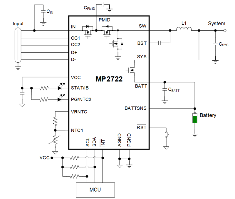
Figure 2 shows a typical application circuit of a 15W, USB Type-C DRP solution with the MP2722, which only requires one inductor and several resistors and capacitors.
Click image to enlarge
Figure 2: A 15W, Integrated, USB Type-C DRP Solution
If the microcontroller unit (MCU) is not necessary, the MP2722 can work as a standalone part, with all the parameters configured by a one-time programmable (OTP) memory unit.
USB Type-C Sink, Source, and DRP Ports
The sink and source ports share a physical receptacle on the USB Type-C port, which is different from traditional USB Type-A and Type-B ports. According to the USB Type-C specification, a sink port should provide a pull-down resistor (Rd), typically 5.1kΩ, on the CC1 and CC2 pins, and a source port should provide a pull-up resistor (Rp) on the CC pins, depending on the source current capability. Rp can also be equivalent to the pull-up current source. The DRP port can support either a source or sink port, meaning Rp and Rd should be toggled periodically on both of its CC pins. Table 1 shows the Rp requirements in source mode.

Click image to enlarge
Table 1: Rp Requirements in Source Mode
After two USB Type-C connectors are connected, one of the CC1 or CC2 pins is connected via the CC channel in the USB Type-C cable. By monitoring Rp and Rd on the CC pins, a USB Type-C device can detect whether a source or sink is attached and set the proper input current limit (IIN_LIM) based on different Rp values in sink mode.
Figure 3 shows a model where a source and a sink are connected via a USB C-to-C cable, where Ra represents the resistance of the e-mark IC in the cable when its power supply (VCONN) is not applied.

Click image to enlarge
Figure 3: USB Type-C Pull-Up/Pull-Down Model
Legacy Cable
A legacy cable is a cable with a USB Type-C connector at one end and a USB Type-A connector at the other end. These cables enable interoperability between USB Type-C products and USB Type-A products. Since there are no CC pins in the USB Type-A port, the CC1 and CC2 pins in the USB Type-C connector should be pulled up to the VBUS pin via a 56kΩ resistor to assert the default 500mA current capability.A sink port can then follow other protocols, such as USB battery charging specification 1.2 (BC1.2), to draw more than 500mA of current.
DRP Operation with Different Ports
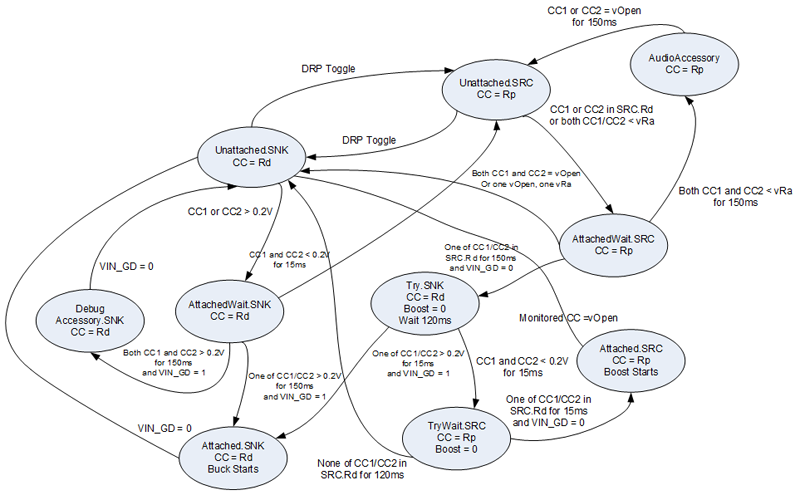
The MP2722 single series cell charger integrates a USB Type-C source/sink detection algorithm, as well as DRP toggling to automatically switch between source and sink mode. Figure 4 shows the state machine diagram for a USB Type-C DRP port, where vOpen refers to the CC pin’s open threshold on the source side and vRa refers to the voltage when the accessory is connected to the CC pin.

Click image to enlarge
Figure 4: DRP Mode
To avoid the random result when two DRP ports are attached to each other, the MP2722 supports Try.SRC and Try.SNK mode to enable the USB Type-C port to operate as a source and sink, respectively, when attached to another DRP port without Try.SRC or Try.SNK enabled. This function is useful when a USB Type-C device strongly prefers to work as a source (e.g. a DRP port in a power bank) or sink (e.g. a DRP port in a mobile phone).
Figure 5 shows the state machine diagram for a USB Type-C DRP port with Try.SRC enabled.

Click image to enlarge
Figure 5: DRP Mode with Try.SRC Enabled
Figure 6 shows the state machine diagram for the USB Type-C DRP port with Try.SNK enabled.
Click image to enlarge
Figure 6: DRP Mode with Try.SNK Enabled
Other Key Features of the MP2722
In addition to supporting USB Type-C DRP operation, the MP2722 provides other key features such as legacy cable detection, BC1.2 support, and moisture detection. These features are described in greater detail below.
Legacy Cable Detection
With a standard USB C-to-C cable, the source side requires 100ms to 200ms of deglitch time to turn on the VBUS output after the CC1 or CC2 pin is connected. However, legacy cables do not have a deglitch time, and VBUS is always enabled. The MP2722 can detect whether it is connected to a legacy cable and inform the host using an interrupt signal.
BC1.2 Support
According to the USB Type-C specification, a legacy cable must pull up its CC pins to VBUS via a 56kΩ resistor. This means the sink can draw a maximum 500mA current only if CC detection is applied, even if the adapter can support higher output current (IOUT) capability. The MP2722 supports BC1.2 detection to draw higher current from the source and shorten the charging time.
Moisture Detection
Moisture in the USB connector may cause corrosion over time and lead to open or shorted pins in the connector. The MP2722 can test the input impedance of a USB Type-C port by sourcing a current on VBUS when no source is connected. If moisture is detected in the connector, the host can alerts the user to take further action.
Prototype of a 15W, DRP USB Type-C Solution with the MP2722
Figure 7 shows the EV2722-RH-00A, a prototype of the 15W, DRP USB Type-C battery management solution.

Click image to enlarge
Figure 7: Prototype of 15W, DRP USB Type-C Solution with the MP2722
The inductor (L1) is 1μH and can be calculated with Equation (1):
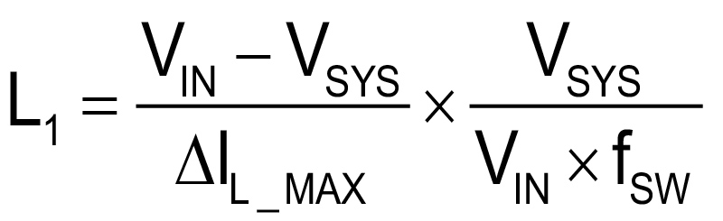
Where VIN is 5V, system voltage (VSYS) is 3.7V, switching frequency (fSW) is 1MHz, and inductor current ripple (ΔIL_MAX) is 5A x 20%.
The input and output capacitors absorb the high-frequency switching current ripple. For the MP2722, the input capacitance (CIN) is 1μF, the PMID capacitance (CPMID) is 10μF, the system capacitance (CSYS) is 20μF, and battery capacitance (CBATT) is 20μF.
Figure 8 shows the CC1 and CC2 waveforms when no source or sink is attached. The MP2722 toggles Rp and Rd across an 80ms time period.

Click image to enlarge
Figure 8: CC1 and CC2 DRP Waveforms of the MP2722
Figure 9 shows the waveforms when a source or load is attached in DRP mode, where the MP2722 is set to DRP mode with no Try.SRC or Try.SNK, battery voltage (VBATT) is 4V, charge current (ICC) is 2A in sink mode, IOUT limit is 3A in source mode, and the CC1 pin is connected to the USB Type-C cable’s CC channel. Figure 9a shows the waveform of a 5V/3A source (Rp) attached, and Figure 9b shows the waveform of a 1A load (Rd) attached.

Click image to enlarge
Figure 9: Source or Load Attached in DRP Mode Waveforms
Figure 9 shows that a source is attached when the MP2722 toggles to Rd on its CC pins. The attached source detects Rd on the MP2722 and enables the output, then the MP2722 starts charging. Figure 9b shows that a sink is attached when the MP2722 toggles to Rp on its CC pins. Once the MP2722 detects external Rd, it enables the output after a deglitch time of 150ms. Note that the battery current (IBATT) is negative, which means the battery is discharging.
Figure 10 shows the waveforms when the MP2722 is connected to another DRP port, and Try.SNK or Try.SRC is enabled.

Click image to enlarge
Figure 10: Try.SNK and Try.SRC Waveforms of the MP2722 Connected to Another DRP Port
Figure 10a shows what happens when the MP2722 with Try.SNK enabled is connected to another DRP port (see Figure 6 for more details). Once the MP2722 is connected to the external Rd, it enters a waiting state. Next, the MP2722 enters the Try.SNK state and pulls down CC1 and CC2 via Rd. Finally, the MP2722 works as a sink to charge the battery.
Figure 10b shows what happens when the device with Try.SRC enabled is connected to another DRP port (see Figure 5 for more details). Once the MP2722 connects to the external Rp, it enters a waiting state until VIN is detected. Then the MP2722 starts up Try.SRC by pulling up CC1 and CC2 via Rp. When the external port detects Rd on the MP2722 disappears, it disables the output and pulls down CC1 and CC2 via Rd. Finally, once the MP2722 detects the external Rd, it enables the output and works as a source. Note that the negative IBATT means the battery is discharging.
Conclusion
Compared with traditional discrete solutions, designing an integrated battery management solution using a single series cell charger such as the MP2722 requires fewer external components, which effectively reduces PCB size, simplifies the design process, and shortens the design cycles. The MP2722 also offers advanced features, including legacy cable detection, BC1.2 support, and connector moisture detection, to achieve improved system compatibility and safety. These features make the MP2722 well-suited for building a low-cost, 15W, dual-role USB Type-C charging solution.
For more details, explore MPS’s battery charger solutions, including single series cell chargers, two series cell chargers, and three or more series cell chargers.