
Collateral power system safety standards empower and expand home-based patient care
Figure 1: Equipment designed for clinical settings may not be suitable for home healthcare applications. Certification to the 60601-1 general standard may be acceptable,but it is critical to consider the new requirements of the collateral standard as well as the constraints of a 60601-1-1 general standard certified power converter
The recent pandemic has driven medical facilities around the world to the brink; hospital beds have been earmarked, and ultimately filled, to treat and care for Covid-19 patients while others with “less life-threatening” conditions have either been asked to wait it out or risk their own health at those same facilities in which tests and treatment are being administered. While these patients require care, not all need to be in the presence of a physician to receive it. This, along with an ageing population and the rising costs of hospital-based care, is driving growth of remote healthcare management.
With the convenience of remote or home-based care comes a challenge though; regulatory authorities (and OEMs) must determine fitting safety considerations forthese technologies. In contrast to a hospital or traditional healthcare facility, a patient’s home is an uncontrolled venue where no skilled equipment operators are present and proper electrical installation is not a given. With this in mind, additional measures are critical to ensuring safe use of medical electrical equipment – now standardised asthe 60601-1-11 collateral constraints for medical electrical equipment and systems deployed in a home healthcare setting.
Factors in low-line operation
The 60601-1 general standard presumes a 10% tolerance from nominalfor supply mains – safe performance on input voltages ranging from 90Vac to 264Vac (100Vac-10%, to 240Vac+10%) is mandated for any device’s use on supply mains ranging from 100Vac to 240Vac (Universal Line). While a ±10% tolerance on the mains supply voltage is a realistic expectationfor a regulated medical setting, the potential for variance in mains voltages is greater in uncontrolled or less traditional healthcare settings. The 60601-1-11 collateral standard recognizes this, allowing a tolerance of +10%/-15% for nominal mains voltage, comparable to universal line input deviceswith operational input voltage ranges of 85Vac to 264Vac.
Increased primary-side currents are the initial and most apparent result of the power converter’s lower-line operation requirement. The following formula demonstrates the input current of a converter, illustrated as a calculation of output power, efficiency, power factor, and line-voltage:Output power in Watts is represented by Pout , power factor is denoted by pf, and conversion efficiency is signified by η.
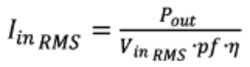
The equation considers that efficiency and power factor are each independent of line voltage. This is not typically true but simplifies our exchange without blurring the implications, and allows that input current for a given load is inversely proportionate to line voltage.
Therefore, line voltage is reduced by 5.55% (90Vac down to 85Vac) resulting in a ~5.9% line currentincrease. To some extent, these proportions will differ as line voltage affects both power factor and operational efficiency. The main takeaway is that any current margin or thermal (I2R) margin designed into the primary-side components has been greatly decreased if the converter was intended for 90Vac minimum line voltage.
In addition to managing greater primary-side currents, any conversion topology must also consider projected input voltage range early in design development. Input voltage generally relates directly to energy per cycle, and a drop in input voltage (while comprised of current hikes from a power perspective) can reduce the amount of energy transferrable per cycle. When input voltage drops below the expected minimum, power systems face risk of overworked switching frequency, duty cycle, or both, resulting in an inability for the converter to handle its rated load.
Output power derating isthe solution to both dilemmas for a 60601-1 general standard certified PSU (designed for 90Vac-264Vac operation). While the formula above allows calculation of the output power reduction necessary to offset increases in primary side currents,it does not allow for ready determination of the relative impacts on the conversion process itself. The PSU manufacturer should be consulted to determine the ideal strategy for low-line derating.
Adhering to Class II construction requirements
All power converters must a minimum of two means of hazardous voltage protection. User protections in Class I power supplies include a layer of basic insulation and a protective Earth ground connection, ensuring a low impedance path to zero potential for fault currents to adhere to. Yet the PSU manufacturer can only ensure a low impedance path up to the PSU AC inlet. In older homes worldwide, Earth ground connections are especially unreliable (if they exist at all) and can be readily bypassed by users. Because of this, OEMs are prohibited from counting on in-home Earth ground connections as one of the two mandated protection mechanisms. IEC 60601-1-11 instead stipulates power supplies of construction Class II, which includeadditional basic or reinforced insulation as a second manner of protection instead of Earth ground. Whether or not a reliable Earth ground connection is present, these power supplies effectivelyprotect users from hazardous voltages.
BF class output considerations
Per Clause 6 of the collateral standard, any applied parts that may be part of the medical electrical equipment must be type BF or greater. Design is further simplified when BF ready power supplies automatically enable the use of type BF applied parts, not a requirement but helpful in streamlining development. While power supplies themselves are not applied parts, the PSU can be appointed to provide the necessary degree of ground isolation as well as appropriate mitigation of leakage currents.
A Construction Class II designation is required for power supplies meant for home healthcare deployment, rendering moot the issue of Earth ground isolation. In contrast, patient auxiliary currents must be limited to 100µAac (and 500µAac under single fault conditions). BF class outputsare not offered in all 60601-1 certified power supplies.
Design for IP21 rated ingress protection
External power adaptor encasements, per 60601-1-11,must provide at least IP21 rated ingress protection in compliance with IEC 60529, and be labelled as such. An IP2x rating signifies that no object with a diameter greater than 12.5mm under a force of 30N or less can penetrate the enclosure. This solid ingress rating is Level 2, intended to ensure that external objects cannot enter the enclosure, for example nothing larger than a child’s finger.
While Level 2 compliance is common, IPx1, or Level 1 liquid ingress protection, is less so. The IEC 60529 test for IPx1, requiring a drip rate of 1mm/min (similar to a light rainfall), may seem inconsequential – yet in the 10 minute timespan of the test, enough water drips off the edges of a power supply enclosure to create system impact. Water accumulating at interfaces with cable strain reliefs, or along the edges of a removable AC blade attachment (in interchangeable wall mount devices) creates enough moisture to cause failure and instability forhome healthcare use. Achieving IPx1 is a readily manageable from an engineering standpoint, and many off-the-shelf 60601-1 power supplies are innately compliant, but compliance should not be assumed.
Enhancing mechanical strength for home performance
In an uncontrolled home environment, medical electrical equipment must remain safe and operational even as it faces greater exposure to mechanical disturbances than equipment deployed in a clinical setting. Children at play or rascally pets may unintentionally knock a device from its platform. A weekend away may mean critical home healthcare equipment becomes portable, transported by vehicle and encountering speed bumps and rumble strips.
Safe and reliable performance of a home healthcare power supply can be validated throughthe following shock and random vibration tests:
Shock: Evaluated per IEC 60068-2-27:2008 with three half- sine pulses of 150m/s2 peak acceleration and 11ms duration through each axis
Vibration: Assessed per IEC 60068-2-64:2008 for 30 minutes per each perpendicular axis
Click image to enlarge
Figure 2: Power supplies used in home healthcare applications must be IEC 60601-1-2 Edition 4 compliant, addressing factors of concern to the uncontrolled nature of the environment. Stringent requirements of the fourth edition include ESD contact discharge immunity of ±8kV, ESD air discharge immunity of ±15kV, radiated immunity for fields of strength up to 10V/m and across a broader frequency range (80Mhz to 2.7GHz), and much more
Powering your next design
Home healthcare is gaining traction, alleviating bottlenecks at hospitals and medical facilities, and lowering costs for providers and patients alike. When taking your medical device to the home healthcare environment, it is imperative to understand IEC 60601-1-11 and its imposition of an additional 13 clauses over the 60601-1 general standard. Many of these design issues are directly related to careful selection of a suitable power converter. By choosing a partner well versed in the complexities of the IEC 60601-1-11 standard and its impact on power system requirements, your design team can capitalise on expertise in home healthcare power design and advance a more patient-friendly approach to wellbeing.


