Designing the Thermal Path for a Baseplate-Cooled Power Supply

The baseplates provide a thermal path for losses from heat-generating components
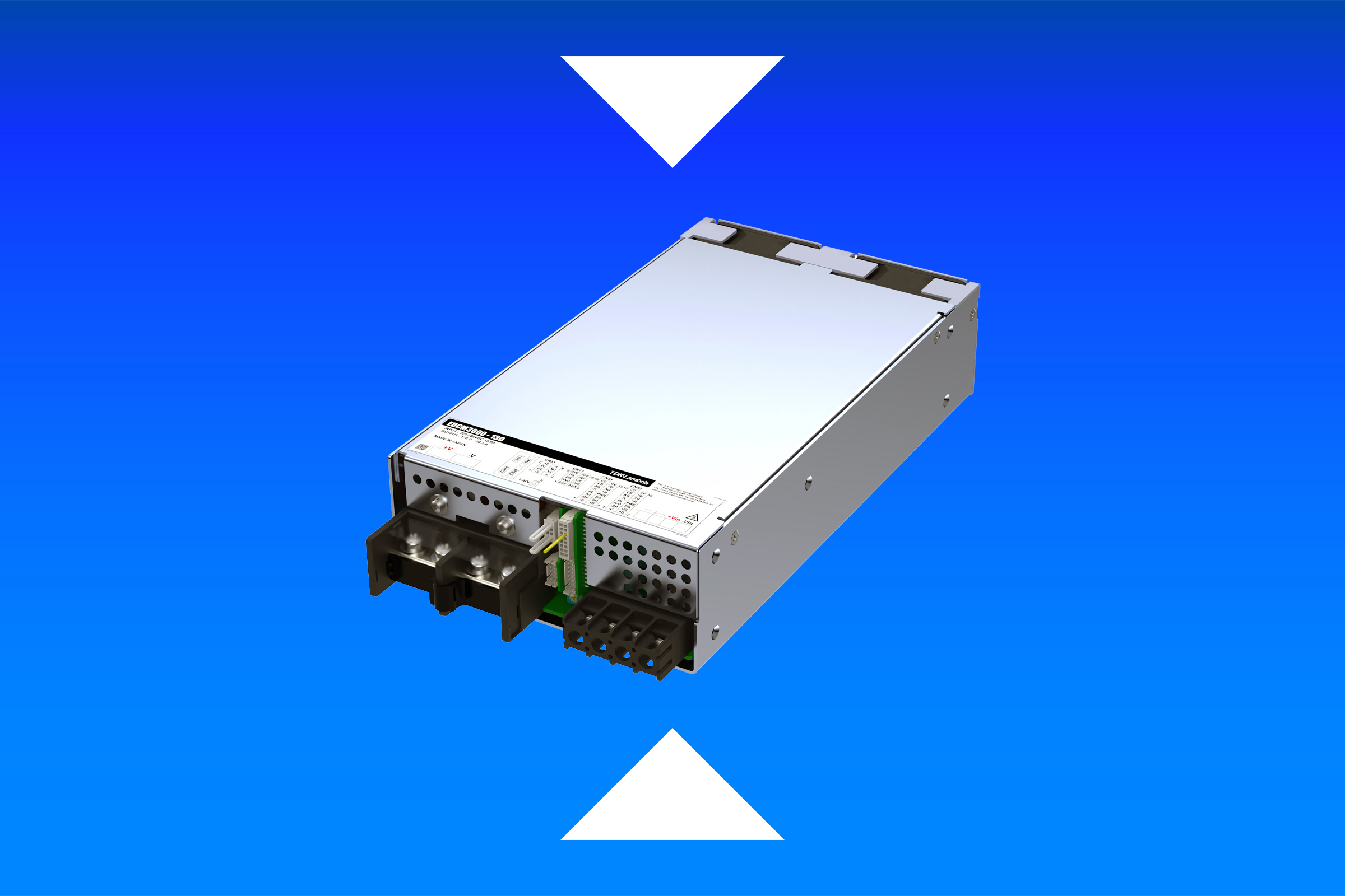
Figure 1: The CCR420 (left) combines baseplate cooling with heat dissipation to the surrounding air while the ASB320 (right) is designed principally for conduction cooling through its baseplate
Choosing a baseplate-cooled power supply is only part of the thermal design. The baseplate provides a thermal path for losses from heat-generating components, but what happens beyond that point depends on the equipment in which the supply is installed. The baseplate may be coupled to a chassis, a cold wall or a dedicated heatsink; whatever the arrangement, it has to carry the losses away without exceeding the specified baseplate temperature.
The effectiveness of that path cannot be determined from the power rating alone. A 300W supply does not have 300W of heat to dispose of: the relevant figure is the power lost in conversion, which varies with operating conditions. The allowable temperature rise also depends on the application. A sealed unit exposed to solar loading, for example, can present a considerably more demanding thermal environment than the nominal outdoor air temperature might suggest.
In a supply designed primarily for conduction cooling, the main heat-generating components can be thermally coupled to the baseplate. Other designs use the baseplate to remove part of the losses, while some heat-generating components continue to dissipate into the air inside the equipment. In the latter case, keeping the baseplate below its specified maximum temperature does not, by itself, show that the complete power supply is operating within its thermal limits.
The power supply architecture sets the starting point
XP Power’s CCR and ASB and series provide useful examples of how the thermal requirements can differ (Figure 1).
The ASB is designed to be only conduction cooled, with the main heat-generating components thermally coupled to the baseplate. For the system engineer, the principal task is therefore to provide the required thermal path from the baseplate to the external environment.
The CCR series combines conduction through the baseplate with convected heat dissipated into the surrounding air. The engineer has two conditions to manage: the thermal path from the baseplate and the temperature within the equipment.
Calculate the losses
Power conversion losses vary with load and input voltage, so the efficiency used for the thermal calculation needs to represent the intended operating conditions. For thermal design, the relevant condition is the one that produces the greatest loss.
Input power can be calculated from output power and efficiency:
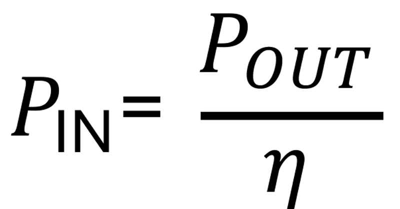
The power dissipated by the supply is then:

To illustrate the calculation, the 48V version of the ASB320 has a typical efficiency of 94% at 230VAC and its full 320W output.
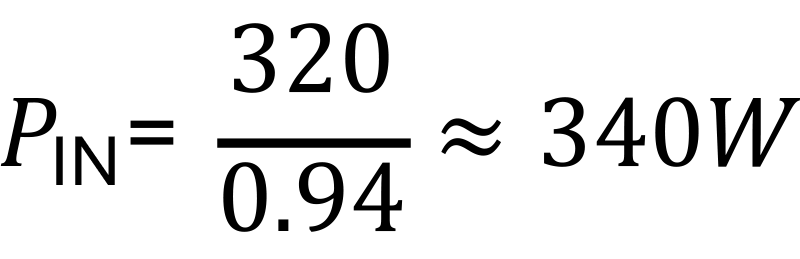
This gives a conversion loss of approximately 20W at the stated operating point, but it should not be treated as the worst-case dissipation. A design intended to operate over a wider input range needs to consider how the losses change across that range.
How much temperature rise is available?
The calculated loss only becomes a defined thermal-design requirementonce the allowable temperature rise is known. For the ASB320, the maximum specified baseplate temperature is 90°C. With an external ambient of 40°C, using that limit gives a maximum available temperature difference of 50°C:
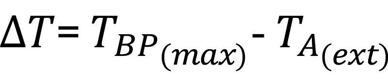

The ambient used in this calculation has to reflect the intended installation. A 40°C air temperature does not necessarily mean that every part of an outdoor installation can be treated as being at 40°C; solar loading can raise the temperature of the enclosure and the surfaces required to dissipate heat. Heat from adjacent equipment may also affect the local thermal conditions.
The 90°C baseplate specification is a limit rather than a reason to design the system to operate at that temperature. Doing so would leave no margin for variation in operating conditions or the thermal performance of the assembled equipment. The appropriate design margin will depend on the application.
Sizing the thermal path
With approximately 20W to dissipate and 50°C between the 40°C ambient and the maximum baseplate temperature, the required thermal resistance can be calculated from:
Using the ASB320 example:
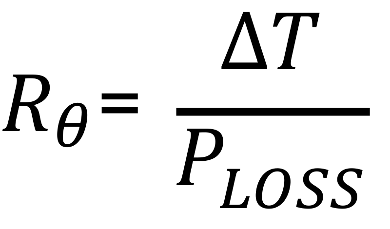
Using the 90°C baseplate limit gives a maximum overall baseplate-to-ambient thermal resistance of approximately 2.45°C/W under these conditions. The individual thermal resistances along the path all contribute to that figure.
A poor mounting interface can consume a significant part of the available thermal resistance.If the baseplate is fixed to a thin sheet-metal panel, for example, panel flatness can limit the actual contact area and introduce air gaps. A thermal interface material can improve contact, although the panel still has to spread the heat into the rest of the cooling structure.
The enclosure has its own heat budget
The calculation above assumes that the losses being considered are removed through the baseplate. With a partially conduction-cooled supply, some of the losses are convected into the equipment and must be included in its thermal design.
The CCR series uses this combination of conduction and convection to support higher power levels than the ASB series. Some of the resulting converter losses must be accommodated within the enclosure.
The proportion of the converter loss that enters the enclosure is not fixed, because it depends on the effectiveness of the conduction path from the baseplate. Reducing the baseplate-to-ambient thermal resistance allows a greater proportion of the loss to be conducted away. In an ideal installation, around 80% of the loss might be removed through the baseplate and 20% dissipated into the surrounding air. This is an indicative example rather than a fixed characteristic, however, since the actual split depends on the thermal conditions of the installation and must ultimately be confirmed in the finished assembly.
For a first-pass estimate of the steady-state temperature rise inside a sealed enclosure, the heat balance can be expressed as EQ_7, where  is the total heat dissipated inside the enclosure, A is the effective heat-dissipating surface area and k is its effective heat-transfer coefficient to the surrounding air. Rearranging this relationship as EQ_8 allows the engineer to estimate the internal heat load that can be accommodated for a specified allowable temperature rise. For a simple sheet-steel enclosure in still air, approximately 5.5W/m²K can be used as an initial value for k, although the actual value will depend on factors including enclosure material, surface finish, orientation and installation conditions. External heat gains, such as solar loading, require a separate allowance.
The portion of the converter loss entering the enclosure must then be added to the heat generated by the rest of the equipment. Where the enclosure and operating environment are already defined, the calculation can instead be worked backwards: determine the total heat load that can be accommodated without exceeding the permitted internal temperature, then establish how much of that thermal budget is available to the power supply.
For the CCR, the baseplate temperature is only one of the limits that shapes the thermal design. The CCR420 datasheet also specifies maximum temperatures for critical heat-generating components that are not cooled through the baseplate (Figure 2). These include selected capacitors and an inductor, as well as a measurement above the transformer.
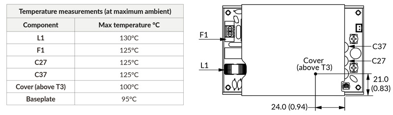
Click image to enlarge
Temperature should be monitored using K-type thermocouples placed on the hottest part of the component (out of direct airflow).
Validation in the finished assembly
The thermal design can only be confirmed in the finished equipment, under the combination of input voltage, load and environmental conditions that produces the greatest thermal stress.
For the ASB series, this means measuring the baseplate temperature at the location defined in the datasheet and checking it against the specified limit.
For the CCR, the baseplate and the additional measurement points identified in the datasheet must all be checked. Thermocouples are attached directly to the specified components where indicated, and each measurement must remain within its stated temperature limit when the power supply is operating in the finished equipment.