Departments
    Technical Features
    Battery-powered equipment benefits from advanced dielectrics

    Designing with low-leakage tantalum and niobium oxide capacitors

    08/13/2012
    Radovan Faltus, Technical Marketing, AVX Tantalum

    DCL (direct current leakage) is an effect common to all capacitors. DCL values and behavior under varying electrical and environmental conditions relate to the capacitor's dielectric. The leakage current in tantalum and niobium oxide capacitors consists of the dielectric absorption current and the fault current that results from impurities and irregularities within the dielectric. Since operating currents in most systems are significantly higher than a capacitor's leakage current, a circuit's functionality remains unaffected by DCL. However, in a battery-operated application the leakage of the capacitor will directly influence standby time, as it directly discharges energy from the battery. This occurs frequently in applications like mobile phones, MP3/MP4 players, DVD players, and in automotive applications where battery-operated wireless sensor transmitters, for example, use capacitors. Battery-powered, handheld equipment commonly use capacitors with 3.7V lithium-ion rechargeable batteries for several functions.

    • Back up data and settings during battery replacement.
    • Smooth the voltage and current peaks during battery insertion, and when the charger connects or disconnects.
    • Support the battery with stored energy when the application's current demand suddenly increases.
    In automotive applications, tire pressure management systems wirelessly transmit pressure and temperature data from in-wheel sensors to a central control unit, which provides information and warning alerts to the driver. This system uses a bulk (parallel) capacitor in conjunction with the sensor to deliver an energy pulse when the measurement or transmission sequence is initiated, especially at low ambient temperatures. Often specified for tire pressure warning systems because of their exceptional operating life of more than ten years, lithium batteries function well at low temperatures. However, under such conditions, they may exhibit an increased internal resistance that can result in a larger voltage drop. Capacitor requirements The suitable nominal capacitance value for battery circuits is typically in the range of 22 to 220 μF. A small-footprint, low-profile device is a common requirement to match the small size of the end device. Excellent performance at extremely low temperatures is an obvious necessity to ensure portable devices' reliability. Tantalum and niobium oxide capacitors make excellent choices for such applications. Designers must minimize standby power consumption to extend battery life. You must consider both active parts and passive functions and, since the leakage current of the bulk capacitor directly drains a battery, reducing DCL is important. Selecting the correct tantalum or niobium oxide capacitor is imperative to minimize leakage current. Different formulas exist for the various capacitor families to determine the basic DCL, which capacitor manufacturers specify at full rated voltage and room temperature:

    where C is the nominal capacitance, VR is the capacitor's rated voltage, and k is a dielectric-dependent constant. For example, values of k corresponding to three of AVX's capacitor series are:

    • TAJ series (tantalum): 0.01
    • TRJ series (tantalum): 0.0075
    • NOJ series (niobium oxide): 0.02
    Ambient temperature and voltage derating are important factors when calculating DCL. Leakage current is proportional to temperature, which manufacturers typically specify at 20 °C. See the manufacturer's datasheet for derating curves to calculate the temperature-related leakage factor. Similarly, leakage current is proportional to operating voltage. The extent to which leakage current at V < VR is less than the leakage at VR differs by capacitor construction (Figure 1). This relationship is an approximately linear measure by reverse decimal logarithmic function with offset (Figure 2)

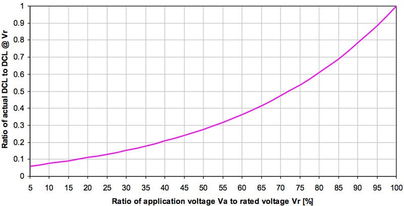
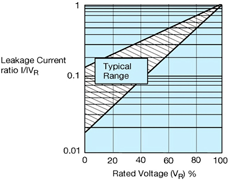
    Optimal voltage derating for minimal DCL To achieve the optimal leakage current ratings for the application (DCLA) at room ambient temperature, we need to consider two factors: the basic DCL defined at rated voltage (Vr as in Eq 1); and the DCL ratio versus voltage derating, as shown in Figure 2:

    where RI is the ratio of DCLA:DCL at VR k are the dielectric-dependent constants given with Eq 1.

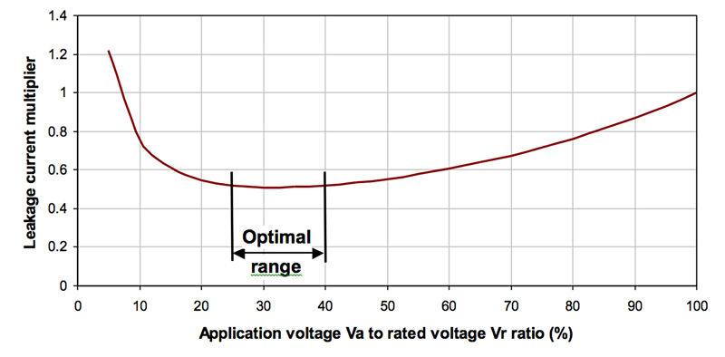
    Figure 3 shows The maximum DCL multiplier versus VA/VR for a fixed application voltage VA. The maximum DCL value varies with capacitor type, nominal capacitance, and rated voltage. The shape of the graph will be the same, so you can identify the range of Va/Vr (derating) values with minimum DCL as the ‘optimal' range. Therefore, you'll obtain the minimum DCL when a capacitor is operates at 25 to 40% of its rated voltage, which translates to a rated capacitor voltage 2.5 to 4 times higher than the application's operating voltage. Comparison in typical battery circuits The typical energy source of a handheld device is a lithium-ion rechargeable battery with a nominal voltage VA = 3.7V. To support device functionality, designers can choose from several different capacitor series.. Where the VA is 3.7V, the optimal rated voltage, VR, is 10V, (which means optimal operating conditions are at 37% of rated voltage. This ratio of VR:VA is independent of capacitance. www.avx.com

    Related

    Transformer Design Comparisons for Mitigating EMI in Gate Driver Circuits

    Mar 29,2026
    Matthew Russell, Master’s student at University College Cork, and a student engineer at Bourns Electronics Ireland

    Integrated On/Off Controllers Help Energy Efficient System Designs

    Apr 1,2026
    Bryan Angelo Borres, and Noel Tenorio, Analog Devices

    Helping to Rewire Aerospace

    Apr 1,2026
    Bo Corn, Strategic Advisor, WireMasters

    SMD PIR Sensor Enables the Next Generation of Smarter Living

    Apr 1,2026
    Yoichi Fujioka, Director, Product Marketing at Murata Manufacturing Co., Ltd

    Power Systems Design

    146 Charles Street
    Annapolis, Maryland 21401 USA

    Power Systems Design

    Power Systems Design is a leading global media platform serving the power electronics design engineering community. It delivers in-depth technical content, industry news, and product insights to engineers and decision-makers developing advanced power systems and technologies.

    Published 12× per year across North America and Europe, Power Systems Design is distributed through online and fully digital editions, complemented by eNewsletters, webinars, and multimedia content. The platform covers key areas including power conversion, semiconductors, renewable energy, automotive electrification, AI power systems, and industrial applications—supporting innovation across the global electronics industry.