Developing BMS Software Faster with System-Level Simulation
Growing dependence on battery pack energy storage has underscored the importance of a battery management system
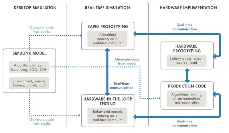
Figure 1. Model-Based Design for battery management system development
The growing dependence on battery pack energy storage has underscored the importance of a battery management system (BMS) that can ensure maximum performance, safe operation, and optimal lifespan under diverse charge-discharge and environmental conditions. To design the software for a BMS that meets these objectives, engineers develop feedback and supervisory control algorithms to:
· Control the battery charging profile
· Monitor cell voltage and temperature
· Balance the state-of-charge of individual cells
· Estimate state-of-charge (SOC) and state-of-health (SOH)
· Limit power input and output for thermal and overcharge protection
· Isolate the battery pack from source and load when necessary
Engineers develop BMS algorithms and software by performing system-level simulation with Model-Based Design. Using simulation enables you to gain insight into the dynamic behavior of the battery pack, explore software architectures, test operational cases, and begin hardware testing earlier in the development process. The BMS simulation model serves as the basis for development activities, including desktop simulation of the design’s functional aspects, formal verification and validation to industry standards, and code generation for real-time simulation and hardware implementation (Figure 1).
Desktop Simulation: Modeling BMS Functionality
Desktop simulation enables you to verify functional aspects of the BMS design, such as charge-discharge behavior, electronic circuit design, and feedback and supervisory control algorithms. On the desktop, the battery system, environment, and algorithms are simulated using behavioral models. You can use desktop simulation to explore new design ideas and test multiple system architectures before committing to a hardware prototype. For example, you can explore active vs. passive cell balancing configurations and algorithms to evaluate the suitability of each balancing approach for a given application.
Modeling and Characterizing the Battery Cell
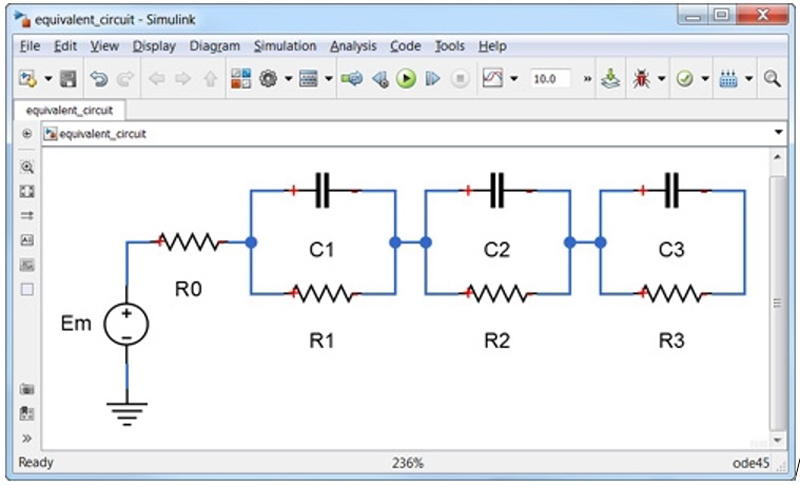
Simulations start with an accurate model of the battery pack, usually an equivalent circuit to simulate the thermo-electric behavior of the battery cell. The equivalent circuit typically comprises a voltage source, a series resistance, and one or more resistor-capacitor pairs in parallel (Figure 2). The voltage source provides the open circuit voltage while the other components model the internal resistance and time-dependent behavior of the cell. These elements are temperature and SOC dependent. Because these dependencies are unique to each battery’s chemistry, they are determined using test data.
Click image to enlarge
Figure 2. Equivalent circuit of a battery with 3-time constants, internal resistance, and open circuit potential
Modeling the Power Electronics and Passive Components
To understand how the BMS copes with changing operating conditions, simulations require accurate models of the circuit components connecting the battery system to the power source and load. System-level simulation lets you model a charging source, such as a photovoltaic (PV) system, around the battery and validate the BMS algorithms under various operating ranges and fault conditions. You can model and simulate the battery pack load, such as a synchronous motor (PMSM) in an electric vehicle operating through a series of drive cycles. Models of active and passive electrical components, such as the analog front end for cell balancing, make up the balance of a complete battery system circuit.
Developing Supervisory Control Algorithms
Engineers develop supervisory control algorithms using state machines and flow charts to model combinatorial and sequential decision logic for fault detection and management, charge and discharge power limitation, temperature control, and cell balancing. The BMS supervises how the battery system reacts to events, time-based conditions, and external input signals. For example, for constant current, constant voltage (CCCV) charging, you can develop and test the logic that controls when the cell transitions from current charging mode to voltage charging mode.
Estimating State of Charge
Traditional approaches to SOC estimation exist, such as open-circuit voltage (OCV) measurement and current integration (coulomb counting). Estimating the SOC for modern battery chemistries that have flat OCV-SOC discharge signatures requires a different approach. Extended Kalman filtering (EKF) is one such approach shown to provide accurate results for a reasonable computational effort. This technique typically includes a model of the nonlinear system of interest (the battery), which uses the current and voltage measured from the cell as inputs, as well as a recursive algorithm that calculates the internal states of the system (SOC among them) based on a two-step prediction/update process.
Estimating State of Health
All batteries degrade due to calendar life and cycling, suffering a gradual loss in reserve capacity and an increase in internal resistance. While the latter is relatively straightforward to estimate using short time measurements, the former requires a full charge or discharge excursion for an accurate calculation, which is not always practical. This challenge has led to growing interest in state of health estimation. Unlike SOC estimation, there is no universal agreement on how SOH is to be defined. General practice is to develop and simulate custom SOH estimation algorithms that are in line with your organization’s specific interpretation of battery health.
Testing with Desktop Simulation
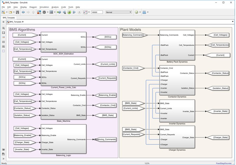
Desktop simulation lets you execute test cases to exercise the BMS along all possible branches of logic and closed-loop control—a level of coverage rarely available when testing with hardware. When the battery system must meet safety requirements, you can integrate tests based on formal methods into your software development process in accordance with standards such as IEC 61508, IEC 61851, and ISO 26262. With this approach, the simulation model serves as an executable specification driving the design and testing of the BMS (Figure 3).
Click image to enlarge
Figure 3. BMS algorithms and plant dynamics, including battery pack, contactor, inverter, and charger, modeled in Simulink
Real-Time Simulation: Validating BMS Software
Desktop simulation models can be used to generate C and HDL code for rapid prototyping (RP) or hardware-in-the-loop (HIL) testing to validate the BMS algorithms using real-time simulation. The objective is to emulate the BMS controller using RP and the balance of the battery system using HIL. Real-time simulation for BMS design lets you:
· Conduct RP to start validating algorithms before the final controller hardware is selected
· Exploit the flexibility of a real-time test system for rapid design iteration and testing
· Conduct HIL testing before the battery system prototype hardware is available
· Use a combination of RP and HIL testing to exercise BMS algorithms for test cases that may be difficult, expensive, or destructive if you were to use the actual hardware
Performing Rapid Prototyping
With RP, instead of handwriting control software code, you generate code from your controller model and deploy it to a real-time computer that performs the functions of the production microcontroller. With automatic code generation, algorithm changes made and validated in the desktop model can be tested on real-time hardware in hours rather than the days it would take to reprogram changes to a microcontroller. Further, most simulation tools let you interact with real-time control hardware to change algorithm parameters and log test data.
Testing with Hardware-in-the-Loop
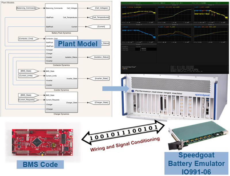
In the case of HIL testing, C/C++ and HDL code is generated from the battery system models rather than the control algorithm models, enabling a virtual real-time environment that represents battery pack, active and passive circuit elements, loads, charger, and other system components. Once you deploy this code to a real-time computer, you can run simulations of the hardware against your controller code before testing the controller in a battery system prototype (Figure 4). As a result, you can find and correct control design errors before they potentially damage expensive and difficult-to-replace prototype hardware. You can also uncover hardware design errors, such as incorrect component sizing. Tests developed during desktop simulation can be carried over to HIL testing, to ensure that requirements are met as the BMS design progresses. Though HIL testing is employed primarily to test code running on a microcontroller or FPGA, you can instead use a rapid prototyping system connected to the HIL setup before production controller hardware is selected.
Click image to enlarge
Figure 4. Hardware-in-the-loop testing of battery management system software. The BMS code is generated from BMS algorithms modeled in Simulink and deployed to a microcontroller. The battery system model is modeled in Simulink. Code is generated and deployed to run on Speedgoat real-time machine with battery emulator
Production-Ready Code Generation
You can use the validated control algorithms as the basis for generating production-ready code—either optimized C/C++ code for microcontrollers or synthesizable HDL code for FPGA programming or ASIC implementation. Automatic code generation eliminates manual algorithm translation errors and produces C/C++ and HDL code with numerical equivalence to the algorithms validated in your desktop simulation. By simulating your control algorithms over all possible operating and fault conditions, you increase confidence that the generated code will handle those same conditions in the real system, even if you are unable to test for all of them. If hardware tests later indicate that algorithm changes are needed, you can simply modify the algorithms in your model, rerun simulation test cases to verify the correctness of the changes, and generate new, updated code (Figure 5).
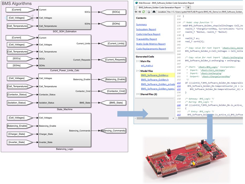
Click image to enlarge
Figure 5. Automatically generating BMS production code from BMS algorithms modeled in Simulink. Code is deployed to Texas Instruments C2000 microcontroller
System-level simulation lets engineers reduce the impact of design errors early during BMS software development. Feedback control and supervisory logic algorithms such as charging and SOC are tested against battery models that represent the characteristics of real batteries. Mistakes can be corrected before testing on prototype hardware. Software code for the BMS is generated from the simulation algorithms and is used for real-time testing and production implementation. This time-saving step reduces testing delays for code updates and eliminates hand-coding errors.
MathWorks