Over the last few years, the industry has experienced a great deal of disruptive change
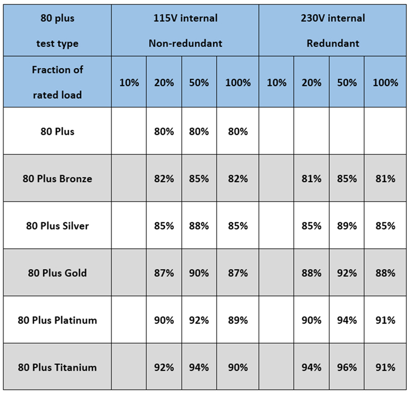
Table 1: 80 plus Efficiency Standard Requirements
The pace and scope of the change overtaking the industry shows no signs of stopping. From advanced robotics, to medical wearables, to the smart grid, the amount of functionality presented to the public today is extraordinary. However, all that functionality needs power.
Power is behind everything in our modern society. Regardless of the core technology, electronic products require electricity to function. It may sound like a tautology, but nothing happens unless you can move electrons around. If it doesn’t have a charge moving around somewhere, it’s a mechanical device.
Artificial Intelligence, Cloud-based IoT, next-gen RF technologies, self-driving EVs, and other advanced solutions have significantly increased the overall global demand for electrical power. This in turn, drives power engineers and architects to extend existing power technology boundaries to achieve ever higher system efficiencies, faster response times, and more robust and reliable solutions.
The plethora of proposed solutions to address power efficiency created disruption in many ways, one of them being the need for standards and regulations. Without agreed-upon benchmarks, it is easy for different companies to claim different benefits out of context to the engineer. Only by ensuring that the lines on everyone’s ruler are the same distance apart can we ensure an open and level development environment.
Addressing power efficiency
In the telecom, data center, and industrial power space, the 80 Plus Titanium efficiency level specification was developed to address power conversion electronics. It specifies over 80% energy efficiency at 20%, 50%, and 100% of rated load, and a power factor of 0.9 or greater at 100% load. The Energy-Star 80 PLUS efficiency specification (introduced in 2007) adds higher efficiency levels for AC-DC supplies from Gold to Platinum and on to the Titanium level.
Other efforts include the Storage Networking Industry Association (SNIA) and their Emerald Power Efficiency Measurement Specification. The specification identifies the metrics by which energy consumption and efficiency of storage networking products can be measured.
Beyond topology innovations, power semiconductor advances have also provided solutions to address power electronics efficiency. Fast-switching wide-bandgap Silicon Carbide (SiC) or Gallium Nitride (GaN) power devices have revolutionized the industry. These new solutions must be properly integrated and optimized for maximum utility, efficiency, and reliability.
In addition, high bandwidth isolated single-chip current sensors in bridgeless Power Factor Correction (PFC) and DC-DC converters can enable use of fast switching wide-bandgap power devices to help improve efficiency and thermal management, reducing both size and component count to simplify PCB circuits as well. This complementary mix of solutions must be properly integrated to address the application in the most cost-effective manner.
Power System Considerations
Efficiency and power density directly impact the size and thermal management requirements of a switch mode power supply.
To meet the 80 Plus Titanium standard, the design must demonstrate 96% Titanium peak efficiency, meaning the target efficiency of Power Factor Correction (PFC) circuit efficiency should be 98.5% under both 115V and 230V input conditions with an overall efficiency of 96%. In order to achieve that goal, one of the most suitable topologies is a bridgeless PFC circuit, which does not require a full-wave AC rectifier bridge, thereby reducing related conduction losses.
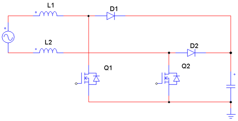
There are two types of bridgeless PFC designs: Bridgeless PFC and Totem Pole PFC (Figures 1A and 1B). Compared to bridgeless PFC, Totem Pole PFC removes the input bridge rectifier and uses a MOSFET to replace the rectifying diode for improved efficiency.
Click image to enlarge
Figure 1a: Bridgeless PFC
Click image to enlarge
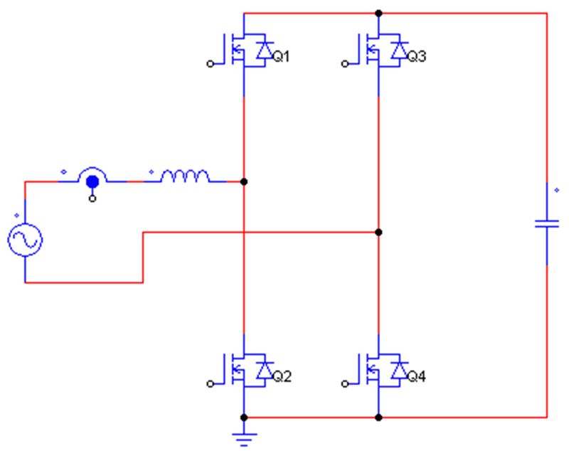
Figure 1b: Totem Pole PFC
Wide-bandgap semiconductors
There is a reason why a SiC-based MOSFET is needed in a Totem-Pole PFC design. As Figure 2 shows, a Totem Pole PFC can be considered as a synchronous-rectification boost DC-DC converter. In such systems, a big problem is the reverse-recovery charge of the MOSFET body-diode, if the converter works in CCM (Continuous Conduction Mode) condition. This means that the Totem Pole PFC can only work in DCM (Discontinuous Conduction Mode) or BCM (Boundary Conduction Mode) mode, with a traditional Si-MOSFET.
Each approach has its challenges. A DCM PFC can only support low-power applications, for example. In a BCM PFC, the frequency varies widely, and the peak current will be 2 times of a CCM PFC, which increases the difficulty of EMI filter design and efficiency optimization. By using wide-bandgap SiC- and GaN-based power switches, Totem Pole PFC designs can successfully operate in CCM mode to provide higher efficiency and power.
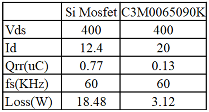
Considering a design of 3.3kW Totem-pole architecture based on SiC MOSFETs, magnetic current sensing, and CCM control, we chose a model C3M0065090K SiC MOSFET from Wolfspeed as the high-frequency switches, and a IXFH80N65X2 device from IXYS for the low-frequency side. The choice of a SiC MOSFET over a GaN MOSFET was made because SiC provides the higher breakdown voltage needed.
Using a SiC MOSFET can dramatically reduce the reverse-recovery loss, enabling the Totem-Pole PFC to work in CCM mode to support higher power levels. Silicon MOSFETs also provide different amounts of body-diode loss. Table 2 compares the amounts of reverse-recovery loss between a Si-based MOSFET and SiC MOSFET, showing the SiC device dramatically reduces both body-Diode and reverse-recovery loss.
Click image to enlarge
Table 2: Body-Diode loss comparisons
Positive Half Line Cycle Operation
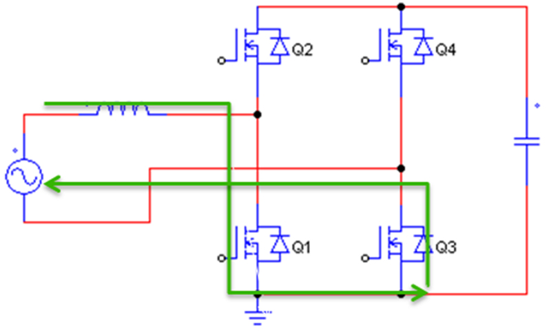
The positive half line cycle operation of the totem-pole PFC is shown in Figure 2. Q1 and Q2 are fast-switching SiC MOSFET devices operating at high carrier frequency, and Q3 and Q4 are traditional lower speed Silicon MOSFET devices operating at 50 or 60Hz. There are only two semiconductor devices in the current path in totem-pole PFC.
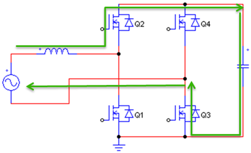
In positive half line cycle operations, Q1 acts as main switch and Q2 acts as a synchronous-rectifier MOSFET, where Q3 is always on and acts as a resistor. When Q1 is on, the ac source stores energy in the inductor, and the output capacitor supports the load current. When Q1 is off and Q2 is on, the ac source and the energy in inductor support the output current and charge the output capacitor.
Click image to enlarge
Figure 2a: Q1 and Q3 on
Click image to enlarge
Figure 2b: Q2 and Q3 on
Negative Half Line Cycle Operation
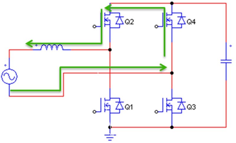
The negative half line cycle operation of the totem-pole PFC is shown in Figure 3. Again, there are only two semiconductor devices in the current path. In the negative half line cycle, Q2 acts as the main switch, and Q1 acts as a synchronous-rectifier MOSFET. Q4 is always on and acts as a resistor.
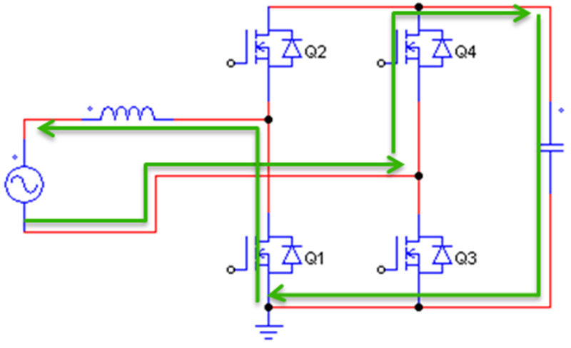
When Q2 is on, the ac source stores energy in the inductor, and the output capacitor supports the load current. When Q2 is off and Q1 is on, the ac source and energy in the inductor supports the output current and charges the output capacitor.
Click image to enlarge
Figure 3a: Q2 and Q4 on
Click image to enlarge
Figure 3b: Q1 and Q4 on
Current Sensing
In PFC applications, average current-mode control is often used because it is simple and accurate. For average current mode control, average inductor current is required for the current control loop. For traditional PFC designs, a shunt is usually placed in the ground line to sense current, as shown in figure 4a. A shunt resistor is used to sense the input current, and an amplifier is used to get different gain. In a Totem-Pole PFC design, there is no ground line and the circuit can’t sample the current.
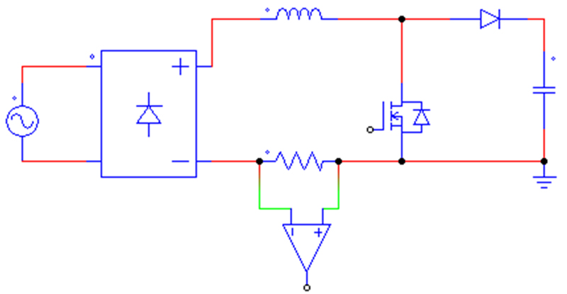
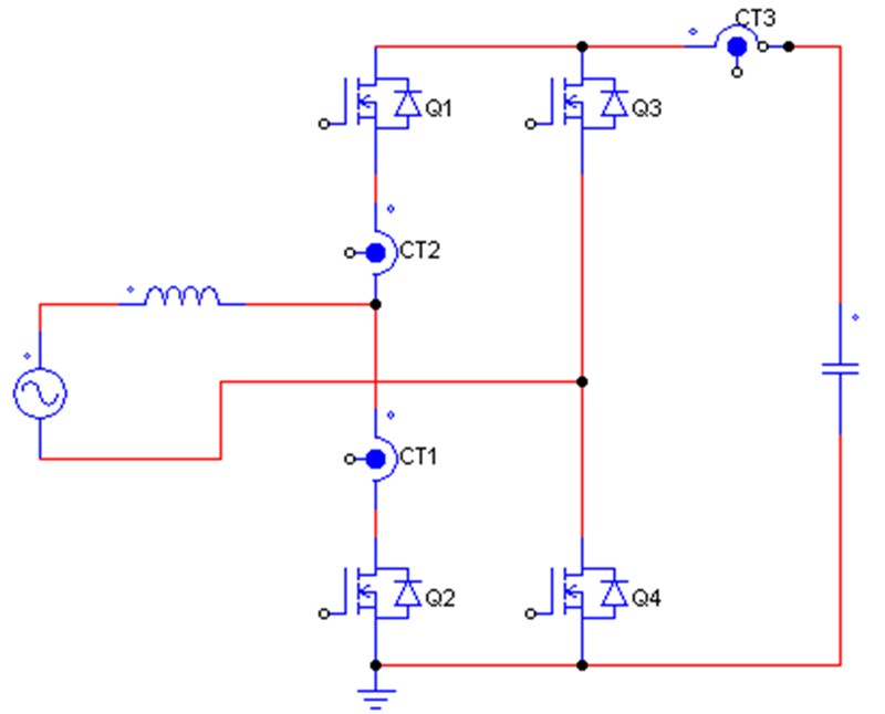
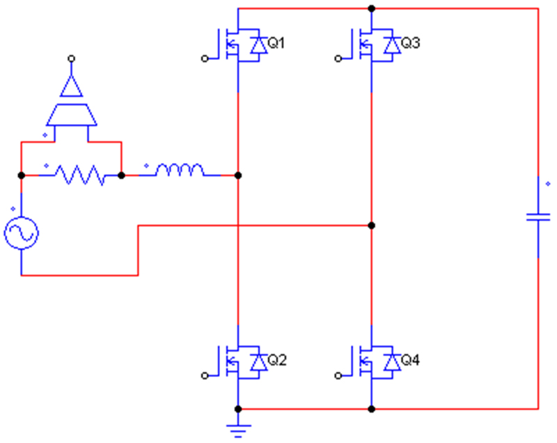
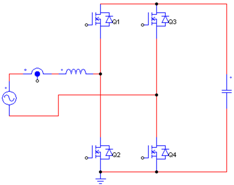
There are several methods to sample the inductor current in a Totem Pole PFC. A Current Transformer (CT), as shown in figure 4b, a shunt resistor with an Op-amp and isolator, as shown in figure 4c, magnetic current-sensor modules, or ICs, as shown in figure 4d.
Click image to enlarge
Figure 4a: Traditional PFC current sensor
Click image to enlarge
Figure 4b: Current Transformer (CT)
Click image to enlarge
Figure 4c: Shunt resistor with Opamp and isolator
Click image to enlarge
Figure 4d: Magnetic current sensor module or IC based on Hall Effect or AMR sensor
A current transformer (CT) can be used to sample the inductor current. Since they can only work in AC, they are better for high frequency designs. To sense switching current, three CTs are needed to sample and integrate the inductor currents in positive and negative cycle through MOSFET and rectifier. Figure 4b shows how CTs provide measurement isolation.
Although separate isolated power is not needed for CTs, the circuit requires three CTs to reconstruct the line current. CTs also suffer from linearity and hysteresis impact over temperature. Other challenges are that using three CTs increases costs and takes up more space.
Another method is to insert a current shunt in series with inductor as shown in figure 4c. This approach requires an op-amp, an isolator, and a separate isolated power supply with multiple passive components around the isolator and op-amp. The circuit design is complex and needs more physical space. Additionally, for higher current applications, using accurate low value resistors to minimize power dissipations are also costly. Further, output response time is limited due to opto-isolator and op-amp on signal path. The combined output step response time can easily be over 1us.
Non isolated current measurement using shunt with an op-amp (without an isolator), typically used in the ground return of traditional PFC, shown in Figure 4a, is not suitable for Totem Pole PFC, which requires isolated current measurements.
An isolated magnetic current sensor module or IC with Hall Effect or AMR magnetic field sensors is an effective and popular method of current sensing. These magnetic current sensors provide the required isolation and do not need separate isolated power supplies. The typical sensor location is shown in figure 4d.
There are two major challenges in dealing with magnetic current sensors. The limited bandwidth of magnetic current sensors is one. The traditional Hall-Effect-based sensor has typically a 120kHz bandwidth, with up to 3db of distortion at 120kHz. Although it can be used for 50Hz PFC current, its slow output response time, related to bandwidth, can’t support peak and overcurrent protection.
For fast-switching current situations, it will cause delay for peak current protection. In practical applications, current measurement is typically done cycle-by-cycle at the middle of the switching PWM pulses. For this, the current sensor needs to support the higher bandwidth needed for measuring current at a high switching frequency in SiC- or GaN-based Totem Pole PFC circuits.
Size counts
Current sensor modules using ferrite cores need to be accurate, with high bandwidth, low phase delay, and fast output response time, for measurement and protection. Typically high bandwidth and accurate current sensor modules are not only bulkier but costlier as well. The size of current sensor modules impacts the space needed, the power density, and the cost of the PFC solution.
In this design, a high accuracy 4.8kV isolated current sensor IC (MCA1101-50-5) from ACEINNA was chosen to sample the inductor current. This +/-50A current sensor IC with 0.6% typical accuracy, 1.5 MHz bandwidth, and output response time of 300ns can fully meet the high frequency cycle-by-cycle current sample measurement and protection requirements in this design@3.
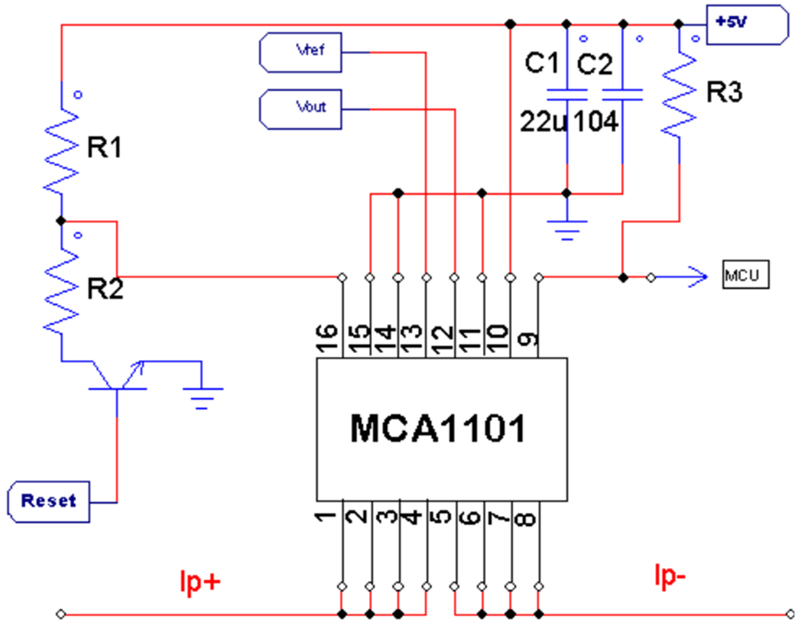
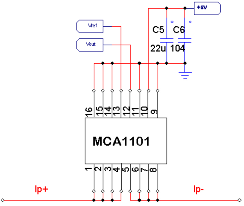
The device offers reinforced isolation and meets UL60950 with no additional isolated power supply. A typical application circuit is shown in Figure 4e. If the internal Overcurrent Detection (OCD) function is not used, only decoupling capacitors are needed, further simplifying the circuit as shown in Figure 4f.
Click image to enlarge
Figure 4e: MCA1101 application circuit with OCP function
Click image to enlarge
Figure 4f: MCA1101 application circuit without OCP function
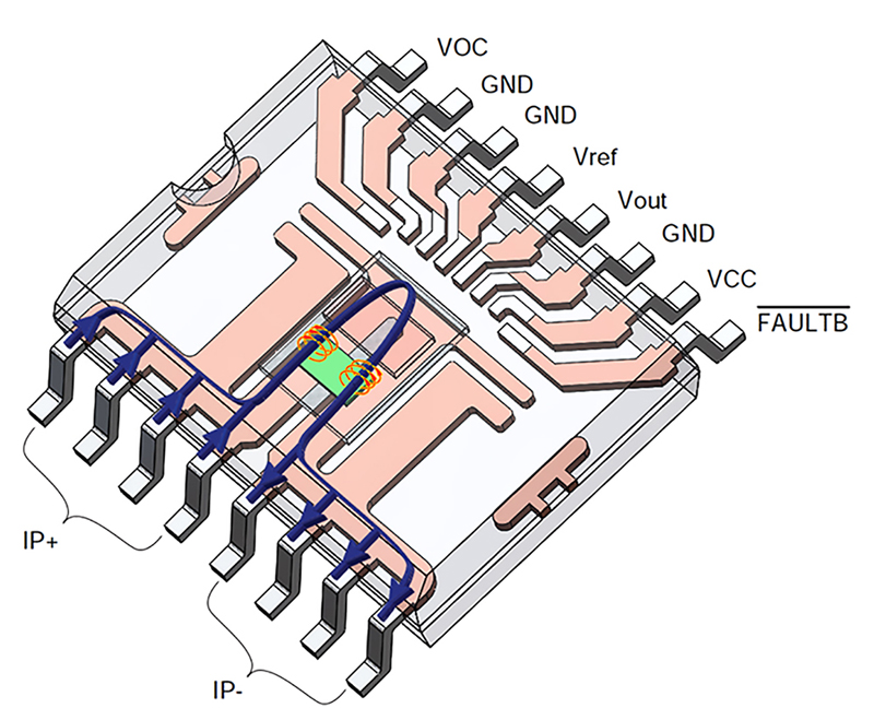
The MCA1101 current sensor IC provides an accurate 0A-reference voltage output pin, which helps to calibrate out 0A offset in the system. The Overcurrent Detection (OCD) threshold can be set on the IC and fault flag pinout can interface with MCU, to trigger the over current protection in the software. This single-chip current sensor solution is in a space-saving package, shown in Figure 5a and 5b.
The MCA1101 provides many advantages for a Totem-Pole PFC application. These include high accuracy over temperature, high bandwidth, fast response, single power supply, reinforced isolation, programmable OCD voltage and fault pin to provide current information to MCU. All of these merits make the AMR based current sensor chip to be an attractive solution.

Click image to enlarge
Figure 5a: MCA1101 current sensor IC
Click image to enlarge
Figure 5b: Inside of MCA1101
Looking forward
Addressing cost effectiveness and standards such as the 80 Plus Titanium and SNIA Emerald Power Measurement specifications requires getting the most out of the existing solutions available. Material and component advances such as wide-bandgap semiconductors and isolated single-chip current sensors can empower efficient topologies like bridgeless Totem-Pole PFC. Use of these technologies will enable higher power densities in smaller footprints, with improved efficiency and thermal management.

Click image to enlarge
Figure 6: Tiny current sensors are essential for the correct operation of power supplies found in a wide range of applications
The growing energy demands of the latest application solutions requires the most efficient and cost-effective power electronics. Understanding the latest core technologies created to address these needs, and how they can be best integrated, will go far towards ensuring the success of your next design.