Saves designers' time for a more stable power supply
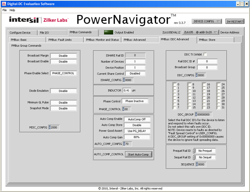
Figure 1: GUI view of Auto Compensation page
Stability is a critical operational requirement for power supplies. In regulated power supplies, the stability is controlled, by a large part, by the characteristics of the feedback path. Power supply engineers need to be conscientious of these characteristics during design to ensure stable operation over all load conditions, environmental conditions, and component characteristic variations. Often, the design of the feedback loop to be stable under all of these conditions is a time consuming task. Depending on the analog filter network used, a number of components may be needed to compensate a conventional power supply. During development, these components need to be selected, procured, and soldered to the board. Many times the component values need to be adjusted to tune the compensator to attain the desired compensation over the full operational space. To further complicate the problem, parasitics play a strong role in the feedback loop. These parasitic elements are challenging to model and are not well controlled for many power components. The load itself is a key element in the feedback loop and many times its characteristics are not well understood. Add the fact that the parasitic elements and the load itself may not be constant valued so the compensation needs to be robust to parametric variations. To further illustrate the difficulty in compensation, consider two situations. In the first situation a high Q (low loss) design can be readily compensated in lab but once the design gets into production, the power inductor can vary in value by +/-10% and the output capacitors can vary by +/- 10%. This can significantly change the control loop even to the extent that the power supply has substantially degraded stability. In the second situation, consider equipment designed for outdoor applications and used electrolytic capacitors in the output filter stage. During the winter, cold electrolytic will have high ESR and low capacitance until they warm up and then the ESR will fall and the capacitance will rise. This, again, significantly changes the feedback loop and can lead to degraded stability. For over a decade now, digital power solutions have provided an alternative to analog compensation. Since an analog compensation network is simply a filter network, the digital filters in a digital power controller can be used for the filter/compensation element. This means that the compensation has no external components and can be tuned by changing the gain values stored in digital registers. Clearly this offers an advantage over analog compensation in terms of dealing with the external compensation elements. So, digital compensation allows easy tuning of the compensator and is done, in most modern designs, using a graphical user interface (GUI) where gain values are entered using a point-and-click, easy to use tool. Digital filters are not simply replacements of analog filters. Digital filters can perform functions that go far beyond the capabilities of analog filters. For example, in high Q (>0.5) second order circuits, the poles in the plant are complex conjugate poles which may require complex conjugate zeros in the compensation network to effectively compensate. Conventional analog compensators only provide real zeros for compensation. This limits their ability to effectively compensate high Q power supplies. On the other hand, digital filters can easily provide the complex conjugate zeros to compensate high Q power supplies. This means that their compensation starts out more stable than their analog counterparts so they are less affected by component parameter variations. Nonetheless, even this advantage, in many cases is not enough to stabilize and optimize a power supply over all conditions. What is really needed is a method for compensating power supplies that is automatic. In recent years, the digital power industry has focused on this issue of automatic compensation. While a number of papers have been published discussing ideas for automatic compensation, until recently, no parts have been made available. Intersil's Zilker Labs has recently released its ZL6105 which is a full featured, intelligent, digital power supply that does have the capability of automatic compensation. The ZL6105 is based on the popular digital controller line from Zilker Labs and uses an advanced digital algorithm to characterize the plant and to determine appropriate compensation settings for stable operation. These digital controllers use a dedicated state machine for the digital PWM controller and an embedded microcontroller to monitor the circuit, environmental conditions, and configuration profile to setup and modify the state machine operation in real time. During auto-compensation, the microcontroller adjusts the state machine to stabilize the power conversion process. Power train component values are set at the manufacturing stage or change slowly so that the microcontroller can easily accomplish its tasks with little power. Like the other Intersil digital controllers, the ZL6105 can be configured using the GUI interface, Power Navigator™. Power Navigator™ connects to the power supply through a USB to SMBus dongle.
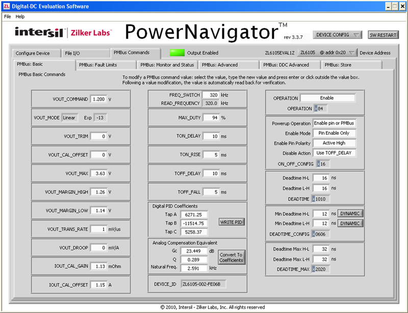
Once connected, Power Navigator™ is used to fully configure the controller and provides telemetry information such as input and output voltage, output current and temperature as provided by the controller. The automatic compensation can also be configured using the GUI interface. Auto-compensation can be configured as desired. Figure 1 shows the view of the GUI, tabbed to the page that allows configuration of the auto-compensation. There are four basic modes that can be selected: off, once, once per second, and once per minute. The "off" configuration disables the auto-compensation. The compensation can be set manually using the options found on a different page within the GUI. The "once" option configures auto-compensation to occur only when (and every time) the power supply is enabled. This is a good option if the primary concern is compensation at time of manufacturing. The "once per second" and "once per minute" options can be used to periodically re-compensate the power supply and is useful when the circuit parameters change over time. While the controller can be configured to automatically auto-compensate, it can also be commanded via PMBus command to compensate itself on demand. Using the GUI, this is done with the push of a button. The auto-compensation configuration has an option to save the compensation values in non-volatile memory. Otherwise the compensation values are stored in RAM. Non-volatile memory has a finite number of write operations so care needs to be used when allowing the controller to save the values to non-volatile memory especially if "once per second" compensation is selected. With auto-compensation configured as "once", the auto-compensation algorithm performs its operation right after the ramp of the voltage, once the power supply is in regulation. The "power good" indicator is usually set to indicate that the power supply is in regulation but it can be configured to wait until the auto-compensation algorithm is complete. A final configuration option for auto-compensation is a gain value associated with the final compensation. Users may want to reduce the control loop bandwidth to balance tradeoffs between transient performance, noise, and stability. The final loop gain can be adjusted in 10% steps from 10% to 100% of full value. Of course, out of the box, the controller is set with default values so that the power of auto-compensation can be used without user interaction. Figure 2 shows the compensator settings, both in terms of the raw compensation gain values and more user friendly values of Gain, Q, and Natural Frequency which more intuitively characterize second order systems. Automatic compensation takes what has been a difficult, time consuming task and reduces it to the simple click of a button or even more simple, a default setting. The patent pending auto-compensation algorithm is designed to be robust even in an environment of changing circuit parameters. An additional benefit of automatic compensation is that the plant is characterized by the compensation algorithm. The values of Gain, Q, and Natural Frequency can be monitored over the life of the power supply and significant changes in the plant can be observed, many times, before failure of the system. This allows the user to incorporate predictive diagnostics of the system health for improved reliability. By saving the design engineer a considerable amount of time, producing a more stable power supply, and potentially improving the reliability with predictive diagnostics digital power with automatic compensation is major technological improvement. www.intersil.com


