On-demand content services are among the factors driving mobile data
The number of mobile broadband subscriptions has grown by around 45% year-on-year reaching 1.7 billion in 2012, according to data released in the latest Ericsson Mobility Report . In addition to this growth, there also is steady progress in the amount of data usage per subscription. The changing habits of people and the way in which they use networks, increasingly using on-demand content services for example, is driving this increase in mobile data. This combined with the growing deployment of the high-speed internet infrastructure via fiber-to-home means that manufacturers in ICT (Information and Communications Technology) applications are being required to develop ever higher performing and higher capacity equipment in a shorter time-to-market, while also implementing the latest hardware and software technologies to ensure low energy consumption.
While this is an extremely challenging situation, it also generates many opportunities to develop new ways of managing board power. For example, moving from passive ‘Board Mounted Power Sources’ (BMPS) that only supply power to loads, to very advanced combinations of hardware and software that make a contribution towards the full integration of board power within the digital chain.
Pushing the limits
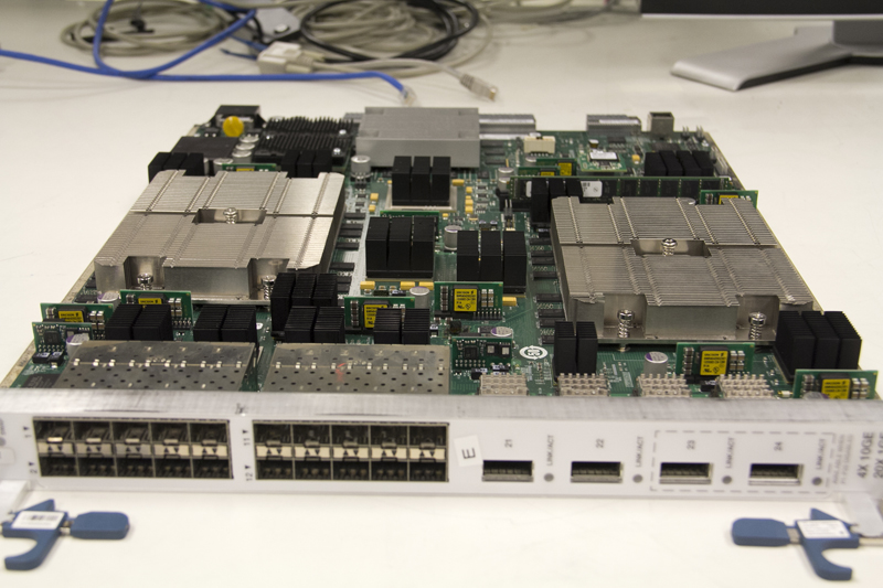
The challenge for the board power system designer is to predict what will be required in terms of increasing power, decreasing board-space, higher flexibility and lower power consumption by the final end-application network data processor. Leading-edge equipment designed to handle high levels of data traffic is often based on multiple cores or processors that are not always fully available at the time of system development. And this equipment requires highly sophisticated power management with power sequencing, monitoring and the capability to dynamically modify an element of the power scheme to adjust to traffic conditions and thereby enable a reduction in energy consumption. An example of this type of complex equipment – an Ericsson high-end subscriber management and routing board – is shown in Figure 1.
Click image to enlarge
Figure 1: Ericsson’s high-end subscriber management and routing board
These types of demands are not entirely new and the BMPS industry is actually quite used to this type of situation. It often faces a wide divergence between the preliminary specifications issued by systems designers and the final end application. And in high-end data processing world, this divergence in terms of power demand and flexibility is reaching an unprecedented level. The time-to-market to support network expansion is becoming ever shorter, while the increase of computing power per network controller is running at a similar rate. Board system architects therefore often find ‘moving goalposts’ when estimating power demand via simulation to match the power required by the actual end application when the system processors reach production maturity.
Complex sequencing is fun
Because network-processors are very complex – and each new evolution integrates more functionality – the current required by the processor could increase by up to 60% from the preliminary specification of the processor to the mature version. Clearly, an evolving processor makes it difficult for board power designers to define the most efficient power architecture for the application. In addition to the increase of power required by the processor, revision after revision, the voltage sequencing is crucial and also has to evolve in step with the development of the processor. This means that designers will have to reset the voltage-sequencing scheme with each new revision.
Furthermore, as well as the power and sequencing plan, when the board is finally released, during the lifetime of the equipment, network processors will be subject to firmware upgrades that may require different sequencing values to optimize operation and reduce energy consumption. In this type of application it is problematic in the extreme to use conventional power architectures, such as implementing analog point-of-load (POL) regulators with a sequencing setup via physical resistors, which will require hardware modifications and make lifetime upgrades almost impossible.
To solve the complex equation of setting the power architecture in parallel with the application development, and to guarantee full lifetime optimization, board power designers are increasingly implementing digitally controlled power architectures that combine digital POL regulators. These can be paralleled to achieve the level of power required by the processor (see figure 2), in conjunction with the flexibility offered by programming the setup sequencing using software such as Ericsson Power Designer (see figure 3), which makes it possible to create specific configurations for power rails and to modify configuration at any time without requiring hardware changes.
Click image to enlarge
Figure 2: A digital POL regulator in single in-line packaging saving board space and improving cooling
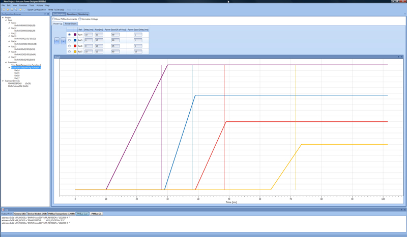
Because varying type of processors and other strategic components such as memories require different types of sequencing on the same board, power architects have often to set up different sequencing schemes, such as Time Based, Event Based, Group Communication Bus Based and Voltage Tracking. As shown in figure 3, setting parameters for any type of sequencing is very simple and can be achieved via software. The example presented in figure 4 shows time-based sequencing in which delays, rise-time and fall-time are based on processor specifications.
Click image to enlarge
Figure 3: Ericsson Power Designer sequencing
Click image to enlarge
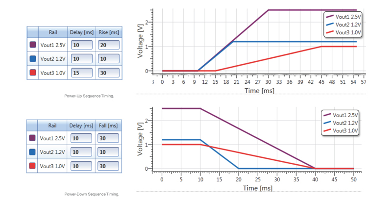
Figure 4: Time-based sequencing – Rise-time and fall-time
In this configuration, the 1.0V core voltage must ramp slowly over 30 milliseconds, while the auxiliary voltages ramp up earlier – within 10 milliseconds – to power supervisory functions, ensuring they are operating before the core turns on. During the shutdown, all voltages are switched off at the same time, within 10 milliseconds; however, the fall-time is adjusted to guarantee smooth transition until all functions are switched off.
As mentioned previously, during the design of the equipment, parameters are evolving and, in case of any different required sequencing, power architects can simply modify the value and send a set of commands to load into the POL or a new configuration file into the Board Power Manager in only a few minutes. The same is possible when the system is in operation and a firmware update that requires different voltage sequencing is recommended for performances optimization.
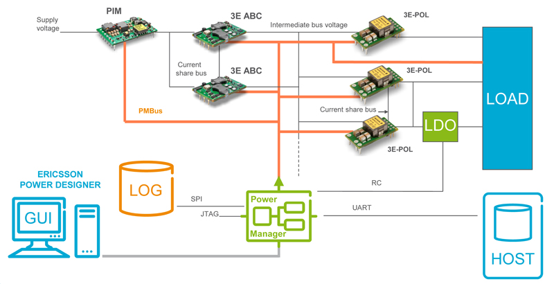
As shown in figure 5, systems using digital power architecture are extremely flexible and the site manager can access any part of the board, down to a single POL through the digital interface.
Click image to enlarge
Figure 5: System overview
Powering the core while saving energy
Over many years the semiconductor industry has drastically optimized energy usage with built-in processor energy management that has significantly improved performance and reduced energy consumption. We all see the benefits of this in our smartphones, tablets and laptops. However, the high-end processors used in data networking have increased their computing power to reach more than 300-Mbps throughput and the number of cores per processor is increasing and beginning to push the limits of Moore’s Law. An increasing number of cores and more power requires ever-shrinking process technologies, resulting in lower voltages and higher currents.
Core voltage is now in the range of 1V and below, with current up to 90A per processor operating at full capacity, but at 10A and below, when operating in a lower utilization mode. To power processors efficiently, power designers are exploiting another benefit offered by digital power, which is to connect a number of digital POLs in parallel. For example, implementing three 40A POLs to guarantee 100A across all conditions and using the benefits of phase spreading to decrease ripple and noise at full power and phase shading to reduce the number of POLs in operation when not required. Although usually complex to manage, the implementation of this type of functionality with digital POLs makes it very simple in practice.
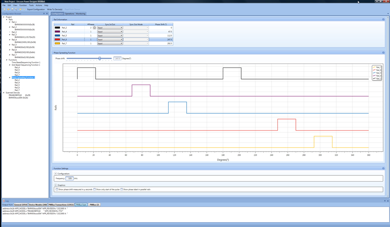
Figure 6 shows how phases can be adjusted when using Ericsson Power Designer. As for the sequencing shown previously, phase spreading and phase shading can be simply programmed. In addition, systems architect can develop multiple configuration files to meet certain profiles that can be called up by the board power manager from local storage. In some applications, the processor directly communicates with the board power manager to set the number of phases required for optimized performances and how those phases should be shifted or synchronized. This simple example provides an idea of the huge potential offered by digital POLs directly communicating with the master processor.
Clcik image to enlarge
Figure 6: Phase spreading
Monitoring and energy reporting
Energy regulations and the growing importance for network operators to reduce energy consumption are adding to the demands upon board power designers to report the power consumption of each board, which requires additional current sensing and other circuitry. As described in the May issue of Power Systems Design, systems architects working on Advanced Telecom Computing Architecture (ATCA) applications are implementing Power Interface Modules (PIMs) with a built-in PMBus controller that is able to monitor current consumption at any time of operation and to report accurate power measurement. The implementation of PIM technology is now spreading to larger number of applications in addition to the ATCA segment.
Current monitoring via the PMBus is available via any digital power module, isolated or non-isolated, simplifying energy monitoring and offering the possibility to supervise the overall system. Digital power modules also include a large number of alarms that can be programmed to report deviation from any default, in addition to temperature monitoring. While it is a clear advantage to know the temperature of the Advanced Bus Converter or POL regulator, the real benefit is to help systems managers to diagnose any abnormal deviation before reaching alarm level. Abnormal deviation from calibrated configuration could easily be the sign of forthcoming failure, trigging a request for preventive maintenance and therefore avoiding traffic disruption and loss of revenues.
Board space saving and temperature mapping
In addition to reducing time-to-market and energy consumption, saving board space to accommodate additional data processing capability is another challenge faced by systems designers. This often comes with another challenge: that of limiting the airflow bottleneck and optimizing cooling to achieve the highest performance from the network processor without overheating.
Saving board space is often achieved by implementing vertically mounted single in-line POLs. In addition to highly efficient power conversion, additional monitoring features built into digital POLs, such as current, voltage, temperature, alarms, parameter settings and many others that are therefore no longer required as separate functions, represent a significant board saving, thereby freeing space for additional computing power.
Gathering temperature information from a large number of points within a board can also be used by systems managers to create a thermal picture of the complete board, which besides detecting early failure is also used to adjust cooling to what is required by the system. In previous generation of systems, thermal mapping relied upon a network of thermocouples requiring additional circuitry, calibration and complexity, which can highly be simplified when implementing digital POLs with this built-in functionality.
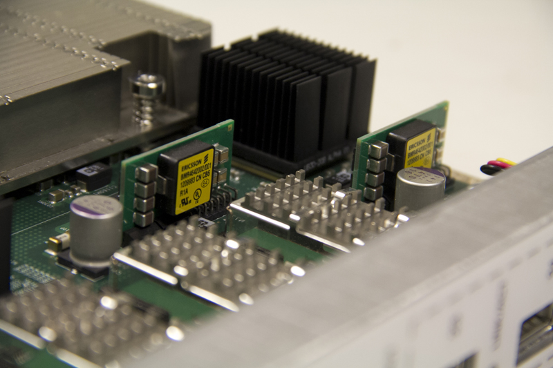
If we consider the high-end subscriber management and routing board shown on figure 1, we can see that the digital POLs (with the yellow stickers) are widely distributed around the board and, understanding that the airflow circulating between and across the heatsink and over the POLs, it is obvious that thermal data collected by each POL represents valuable information for systems architects looking to optimize overall board cooling.