Delivering on the promises
Control of switch mode power supplies (SMPSs) has traditionally been carried out with purely analog circuitry. The advent of low-cost, high-performance digital signal controllers (DSCs) provides a practical route to realizing the benefits of digital power supplies. DSCs can provide an elegant and cost effective way forward to realizing the many benefits of digital power opening up new possibilities for innovation in the power supply world. Some of the benefits include:
- Bill-of-materials (BOM) costs for digital vs. analog power supplies
- Control flexibility and the ability to control advanced topologies
- Implementation of added-value functions without adding to the cost
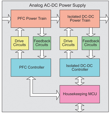
The diagram illustrated in Figure 1 shows a high-level block diagram for a generic two-stage analog AC-DC power supply.
- Power train: semiconductor switches, inductors, capacitors and power transformers.
- Power switch drive: gate drivers and supporting circuitry.
- Feedback: sensors, amplifiers and resistor networks.
- Control: dedicated controllers for each power stage.
- Housekeeping: a dedicated microcontroller and supporting circuitry for sequencing, monitoring and communications.
For the purpose of comparison, a two-stage power supply is considered. The front end converter is a boost power factor correction (PFC) circuit, while the second stage is a DC-DC phase-shifted full bridge converter. Some of these elements, for example the power train, drive and feedback circuits are essentially identical in an analog or a digital power supply. Figure 2 illustrates the corresponding digital power supply for the same example. For the digital version of this power supply, the functions of both the dedicated analog controller, and housekeeping MCU can be combined in a single dsPIC® DSC.

Figure 1 and Figure 2 show only the major differences from a high level perspective; however, all supporting circuitry must also be included in the comparison. Each stage of the analog supply typically requires circuitry to provide auxiliary power, plus leading-edge blanking, oscillator, sequencing control, soft-start, and compensation functions, all connected to a central controller. A digital implementation will still need hardware for auxiliary-power circuitry, but each of the other functions listed above become software running on the central controller. Not only are fewer components required, but physical connections (PCB tracks) are also greatly reduced. Analysis of the bill of materials should consider the cost of this supporting circuitry, layout complexity, and the size of the PCB. Some of the functions identified above may (in the analog implementation) require no more than a few passive components, while others have a higher cost (a separate MCU for housekeeping functions, for example). Some may argue that a digital solution requires the use of dedicated MOSFET gate drivers, while an analog solution may provide the gate drivers on-chip. While this is true for low-power designs, most high-power analog designs will still need to use external gate drivers. A detailed comparison of BOM costs will invariably show a significantly lower total for a digital supply over a comparably-featured analog design. A simple summation of component costs is only part of the story: there are many consequent savings that follow from digital power supplies offering simpler layout, smaller PCBs, reduced PCB fabrication and assembly costs, and improved quality and reliability.
In recent years, continuous improvement in power transistor performance and use of novel topologies, have contributed to significant improvements in power supply efficiency. However, quoted maximum efficiency figures most often apply only at certain specified operating conditions (peak efficiency may be specified at half-load, or at high line voltages). Digital power supplies offer added versatility to optimize the efficiency at multiple operating points. For the PFC boost converter, switching losses can be reduced at lighter loads by operating the converter at a lower switching frequency. Due to the lighter load, the magnetic components will still perform adequately at the lower switching frequencies. If an interleaved PFC converter is implemented, one phase can be turned off at light loads. Similarly, for a phase-shifted full-bridge converter, extra switching losses can be eliminated at light loads by turning off switching of the synchronous MOSFETs, and using the devices' body diodes instead. Another example occurs in a buck converter application. Synchronous buck converters are typically preferred for high current outputs. However, using a synchronous MOSFET leads to circulating currents at light loads, which in turn causes higher losses. Therefore, the synchronous/free-wheeling MOSFET in a buck converter can be disabled when the converter operates in discontinuous-current mode. These techniques supplement the efficiency gains obtained through use of advanced topologies, such as resonant and quasi-resonant converters. Digital control fully supports these advanced topologies, including phase-shifted full-bridge, and LLC-resonant converters, to achieve very high efficiency and power density. As a result, digital control provides many options to optimize the efficiency of power supplies over the entire range of operation.
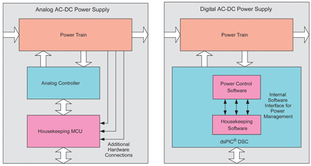
A typical analog power supply will accomplish its power management requirements using a housekeeping MCU (Figure 3). This housekeeping MCU transmits the local system parameters to a master controller or data logger: it uses additional sensing circuits to collect the required data, and then re-transmits it. In some cases, a remote system may also send out instructions to control operation of local power converters. This configuration requires the addition of hardware interfaces between the housekeeping MCU and the power conversion circuits, adding cost and complexity. A digital power supply eliminates the need for this additional circuitry as all of the system parameters are already measured by the DSC. These parameters can be stored in the DSC's memory and transmitted to the remote system using on-chip communication peripherals such as SPI, I2C™, UART or CAN. Any modifications to the system operation can also be made by a simple software routine without additional hardware. The digital power supply also reduces overall cost of the system by eliminating redundant circuitry. In the same example of a two-stage AC-DC power supply, the first stage measures the output voltage for its control loop operations. As this voltage provides the input to the second stage, the same data is also used by the second stage either for feed-forward control or input under/over-voltage protection. A single DSC eliminates redundant measurements, and internally provides all the options for different control or protection features. The DSC also helps the system react to fault conditions much faster and more effectively than with discrete analog controllers. For example, in a two-stage analog AC-DC power supply, if a fault occurs on the downstream converter, the front-end PFC boost converter will not be aware of the fault until this condition has been communicated to the PFC controller. A digital controller can detect fault conditions in the entire system and can therefore react almost instantaneously to a fault regardless of where it occurs.
When a power supply first starts up, the various storage elements, such as capacitors and inductors, contain no energy. To avoid large current and voltage transients, and consequent stress on system components, soft-start is implemented in all stages of the supply. Many (but not all) analog controllers provide a built-in soft-start feature. Analog controllers provide limited flexibility in choosing the soft-start duration and startup delays with additional circuitry. In multi-stage power supplies, there is also a need for sequencing the outputs in a predefined manner, as some outputs are dependent on others. This can be accomplished using a separate sequencing chip, or by using the housekeeping MCU with additional circuitry. A digital power supply eliminates the need for additional hardware because all sequencing and soft-start routines, which can employ a variety of strategies, can be implemented as part of the power supply control software. A soft-start routine can be implemented for each stage of the power supply, in each case combined with a configurable duration and delay. A typical soft-start routine is shown in the C code fragment in Listing 1.
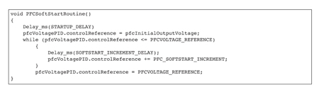
In the code, the soft-start routine is called immediately after the initialization of the dsPIC DSC. A startup delay is first called, and then the output voltage reference is set to the measured output voltage. The reference is then incremented by a fixed amount until the final desired reference is reached. At this point, the soft-start routine ends and normal system operation begins. The digital controller allows for very flexible use of this soft-start routine. The same routine can be called with different parameters at different times. For example, if the system is attempting to restart after a fault has occurred, the startup delay and soft-start duration can be modified to a different value.
Current feedback signals from most power converters must be filtered to eliminate noisy measurements and false tripping of current-limit and fault circuits. Faster switches tend to generate higher levels of noise, and that noise is also present in feedback signals. In some situations, the noise spikes due to MOSFET switching instants may even exceed the maximum current-limit setting. It is difficult to filter out (using analog techniques) this level of noise from the current feedback signal without adversely affecting the wave shape. It is desirable to preserve the wave shape for accurate control loop operations and current-limit protection. Therefore, a technique called LEB is often employed so that the controller ignores the noise spikes on the feedback signal close to the PWM switching edges. For an analog controller, this involves designing a hardware blanking circuit that inhibits response to (or "blanks") the feedback signal for a fixed duration - typically, sensing is enabled by a transistor switch controlled from the power MOSFET's gate drive, via an R-C delay. The delay ensures that measuring circuitry does not "see" the first instants of each conduction cycle. In the dsPIC33F "GS" series of devices, LEB is a standard feature, and the delay is set by a software parameter. The LEB feature can be enabled or disabled at any time and the user can choose which PWM edges to blank out.
With digital power supply controllers comes the ability to change the operation of the power supply at runtime. This capability opens up numerous opportunities for innovation and a chance to gain a competitive advantage over other available products. One of the possibilities for adaptive control is to use multiple sets of control loop coefficients. As the performance of the system changes at different line/load conditions, the coefficients can be modified on-the-fly to achieve the best performance possible at each operating point. As another example, consider that a system is rated for operation up to 50°C; however, for some reason, the ambient temperature exceeds this limit. In this case, the software can be written to reduce the current limit settings. This implementation can help to safely extend the operation of the system beyond its normal limits, albeit with some added restrictions. The introduction of the dsPIC33F "GS" series Digital Signal Controllers has made it possible to achieve all the potential of digital power supply control, opening up new possibilities for innovation in the power supply world. www.microchip.com


