Author:
Laurence McGarry, Power Conversion Marketing Manager and Ken Marasco, System Applications Manager, Analog Devices, Inc.
Date
02/03/2012
 PDF
PDF
Click image to enlarge
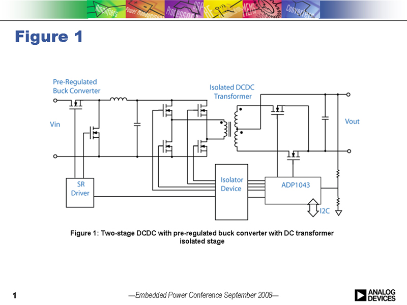
Compared to traditional analog PWM controllers, Digital power controllers provide an extremely high level of flexibility and programmability over the serial interface bus. The designer now has the capability to optimise performance by making changes in software, adjusting the parametric performance of ICs and affecting the functionality of the system. Some examples could include margin and position the output voltage to optimise load performance, changing start-up and shutdown timing to ensure reliable system turn-on and off, altering the control loop compensation to optimise bandwidth and transient response, and fine tuning the timing delays to optimise efficiency. As the system is integrated, it now becomes possible for system architects to make dynamic changes based on the system load behaviour. Some examples could include: dynamic changes of the control loop at different temperatures or load different load conditions; and, dynamic changes to improve the efficiency of the system - changing voltage, delay timing, switching frequency and phase shedding at light load conditions in multi-phase applications. Enabling Energy Efficiency The energy efficiency of a power converter is largely dictated by the topology and then the power silicon, copper PCB and wire and interconnects in the high current path. However, there are some subtle ways that digital power can be used to improve energy efficiency. With reference to Figure 1, here we introduce a two stage DCDC topology, where the input voltage is converted down to a lower fixed voltage, the second isolated stage now runs as an open loop DC transformer with high duty cycle. While the first stage does incur losses, it does regulate changes in the input and allows the second stage to operate at very high efficiency. Results depend on the application and power level but typically around 1% efficiency improvement is achievable in high power ACDC applications. This energy efficient topology is not necessarily new. However, as shown this is controlled by a single digital control and monitor IC, ADP1043A, with few required external components. While the topology is driving the efficiency improvement, it is being enabled, or made possible, in a cost effective way by the use of the digital controller.
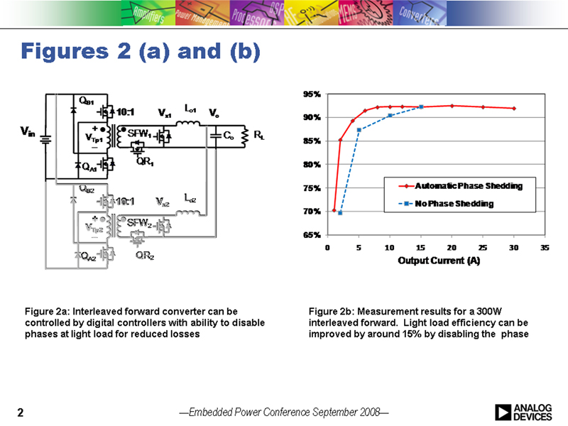
Many end applications never operate at the maximum designed power level. For example, servers typically operate at around 20-30% load. Consequently, it is essential that the power converter operates efficiently across the entire load range of the application. Figure 2a shows an interleaved (two phase) forward converter with synchronous rectification which can be controlled by a digital controller, such as ADP1043A. The converter operates both phases at high load operation but sheds a phase at lighter loads, where it is more likely to operate during the product life cycle. By taking the components out of the power path and by reducing the switching transitions on one half of the converter, significant savings in efficiency can be demonstrated at lower loads as shown in Figure 2b for a 300W converter. Again, this topology is not a new concept but the implementation and the efficiency improvement are enabled by the digital controller, ADP1043A. The digital controller can enable flexible and smooth transitions between states. Further efficiency improvement at low load can be made by utilising the adaptability of the digital controller and finely adjusting the gate drive timing delays between drives. Again, this will help to improve the efficiency over the entire load range.
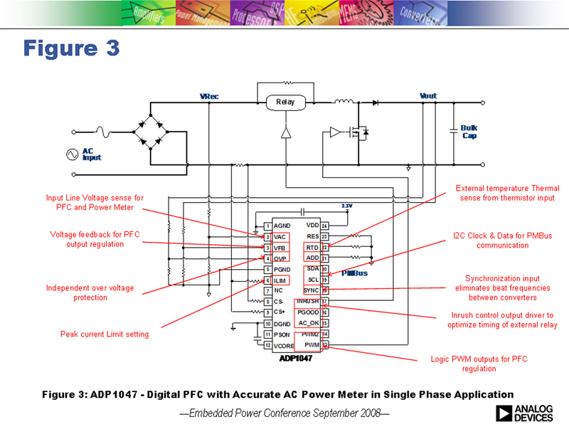
In ACDC systems, system designers add power factor correction (PFC) to meet mandatory power factor and harmonic distortion requirements but also to improve the overall system efficiency. Low power factor increases the peak current and can increase system losses. The use of digital controllers to perform the PFC function and to provide accurate input power measurement has become more popular due to the flexibility and performance improvements achievable. Analog Devices has recently introduced the ADP1047 single phase, digital PFC with accurate power meter followed by the interleaved version, ADP1048, for higher power, compact systems. Both devices enable efficiency improvements at light load by providing programmability over the frequency and the PFC output bulk voltage. An outline schematic of the ADP1047 is shown in Figure 3 with an indication of some of the key features.
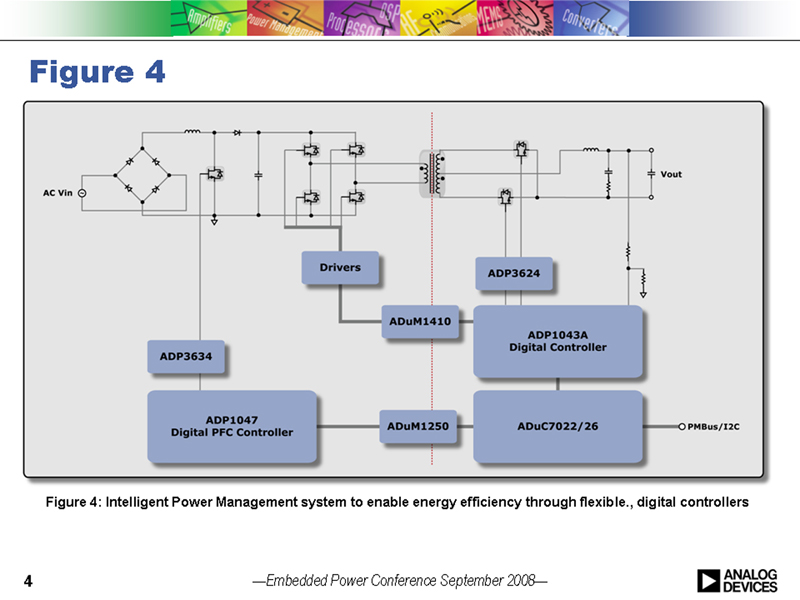
Improving Efficiency through Intelligent Power System Management The ability to read parametric and performance data via the serial interface and dynamically adjust functionality, allows the system architect to implement an intelligent power system to improve the overall system efficiency. A server operating at, say, 20% of its specified load may be supplied by a number (typically 2 or 4) of parallel ACDC power supplies providing N+1 redundancy with forced current sharing to ensure that workload and heat are spread evenly. In this condition, the ACDC supplies are operating well below their optimum operating efficiency. With knowledge of the system load, the system architect can now configure 2 of the 4 ACDC supplies to a high efficiency standby mode while the other 2 now operate at a higher loading closer to their optimum designed efficiency. The net effect is that the overall system efficiency improves without compromising the reliability or uptime. Similarly this concept could be applied to telecom -48V DC input systems that have parallel, input modules current sharing. This concept is being extended to higher level system implementations; workload or power consumption can be accurately measured and communicated to a master controller or system manager allowing workload to be redistributed between system blades or line cards, or between server farms or data centers. Workload can be �virtualised' to improve overall network efficiency and possibly even to improve redundancy and availability of capacity. Intelligent Power Management can be extended to provide a number of other system benefits including: the ability to accurately measure power allows the system architect to apply only the necessary amount of cooling required, thus reducing the power consumption of the thermal cooling system; data recording via the serial interface could store valuable historical performance data to a next generation designer or an engineer analysing failure returns - effectively a power system �Black box flight recorder'; predictive failure capability that flags a system component that must be replaced at next service; and increased resolution for remote diagnosis of failures. The two latter points reduce service time on site and could significantly reduce maintenance costs. Figure 4 shows one implementation of such an intelligent power management solution. In this case, the ADP1047 digital power factor correction controller with accurate power metering controls the conversion from AC to bulk DC. The isolated DCDC is controlled by the ADP1043A digital controller located on the secondary side of the isolation boundary. Both controllers are capable of communicating parametric and performance data. Dependent on the complexity of the data gathering required, an additional micro-controller can be added on the secondary side to communicate with the PFC device and the DCDC controller. ADI iCoupler isolation technology enables high speed communication across the safety boundary.
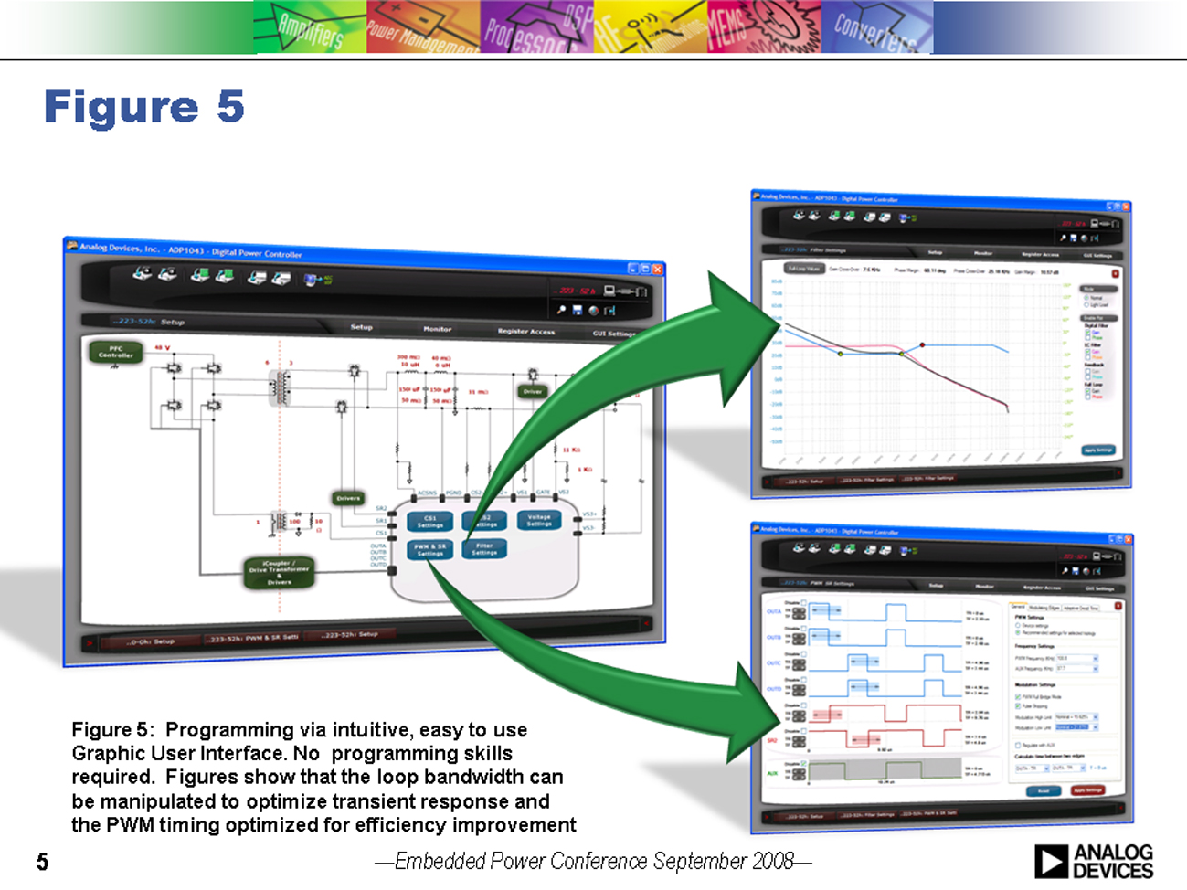
Practical Implementations in Digital Power: Some examples of the new breed of digital power devices are ADI's ADP1043A digital PWM (pulse-width modulation) power control and the ADP1047/48 digital PFC with accurate power metering. These new devices provide designers with highly integrated circuit architecture and the flexibility to configure system power-supply parameters in a matter of minutes using an intuitive GUI. Power design engineers with no prior programming experience can use the GUI to monitor and quickly adjust power functions such as frequency, timing, voltage settings and protection limits. Figure 5 presents some screen shots of the easy-to-use, windows based GUI. The user enters GUI with the familiar schematic of a power supply and can then choose which feature should be adjusted. For example, the bandwidth of the power supply is modified by changing the position of the poles, zeros and system gain. The switching converter topology can be selected and the timing adjusted for optimum performance. All the changes are made easily from the engineers' computer - changes can be made dynamically while the system is operational. In effect, the designer can observe real-time the impact of changes being made. www.analog.com