Direct 48 V to Intel VR12.0 DC-DC conversion
Saving Big Data $500,000 per datacenter, per year
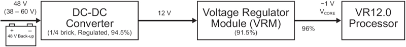
Figure 1: Traditional high-power server architecture showing the two-stage (48- to 12 to 1-V) approach, the wide 48-V input range (38 to 60 V), and back-up energy storage at 48 V.
The exponential rise in Big Data generation, processing, and storage from sources such as intensive industrial simulations, medical research, and social-media sites highlights the growing demand for datacenter and cloud computing power worldwide. The subsequent task is to maximize energy efficiency thus saving money and natural energy resources, minimizing pollution, and meeting the US Department of Energy's Exascale challenge: perform an ExaFLOP (1018 floating-point operations per second) of compute workload using only 20 MW of power. For the power semiconductor industry, the challenge is to provide efficient and high quality power conversion from 480-V 3-phase AC power entering the datacenter, all the way to 1-V, > 100-A processors. Here, high quality means providing the optimum voltage and current as the processor dynamically demands to operate at peak performance. High-volume data processing and data communication tasks require large-scale dedicated, optimized datacenters designed and operated by companies such as IBM, Amazon, Cisco, Hewlett-Packard, Google, Cray and others. Within the datacenter infrastructure, classical physics principles dictate that power should channel to data-processing locations at a high voltage to reduce current and so minimize distribution I2R losses. Compute density (related to the number of processors, the amount of memory, and input and output functionality) and subsequent power draw are also key issues. As power per rack increases above 10 kW, loss in traditional 12-V rack distribution becomes excessive, with additional financial- and size-related costs such as larger, more expensive copper bus bars and connectors. Applications approaching 20 kW and above per rack require efficient 48-V distribution. An example is the POWER7-based IBM Blue Gene/Q, which uses 48-V distribution, 80 kW per rack, and is amongst the world's highest performance and most efficient supercomputers, achieving 20,132 TFLOPs and 2,026 MFLOPs/W. In addition, high-reliability or high-uptime servers require an energy storage system (typically lead-acid batteries) to provide back-up power in the event of a main AC-feed interruption. Historically, small 30- to 40-W ASICs performed processing tasks such as switching and routing in the telecommunications industry. With the rise of triple-play (voice, video, and internet) usage on mobile phones and tablets, voice-only telecom equipment has become datacom, with the use of standard computing processors. These systems typically use a 48-V rail but in central office equipment, the battery back-up voltage may be much wider, requiring wider input-range converters, further reducing the system efficiency. Energy storage is proportional to voltage squared, so 48 V is, again, the superior choice. Voltage regulation Compute workload varies with time. As demand increases, each processor requires more power to maintain performance (MFLOPs). As workload reduces, the processor may throttle back, moving to idle or sleep states to conserve power. In anticipation of a change in power requirement, the processor sends a serial VID (voltage identification) code to the power delivery system. During all steady-state and transient periods, the voltage delivered to the processor must remain within tight, pre-defined limits to maximize performance and minimize the chance of a system crash. VR (voltage regulator) specifications identify power requirements for Intel processors. The Sandy Bridge and Ivy Bridge processor chip-sets require compliance to the VR12.0 specification. Traditional 12-V limitations As power per rack increases, imposing a 48-V rack-distribution requirement, traditional 12-V to VR12.0 power converters require a separate 48- to 12-V conversion stage (figure 1). It is critical to consider the power scheme in its entirety. Headline specification claims for DC-DC converters and VRMs ignore losses related to distribution loss on the motherboard and any connector losses. An accurate approach requires a measurement from the 48-V rail all the way to the processor socket, thus taking into account all potential loss elements. For example, the 96% in the figure accounts for the loss in the motherboard, due to the VRM being large and unable to be located adjacent to the processor socket.
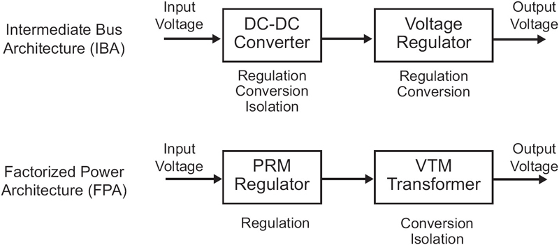
An optimized 48-V alternative Alternative architectures, such as the FPA (factorized-power architecture), employ different approaches to power conversion. The FPA architecture takes the regulation, isolation, and voltage transformation functions of a typical DC-DC converter and separates or factorizes them into individual elements implemented as VI Chips. A power-subsystem design then arranges these individual components (small, high-efficiency regulators and transformer / isolators) in the optimal power architecture (figure 2). For example, VI Chip PRM regulators use a non-isolated buck-boost topology. The PRM accepts a varying DC input and creates a tightly regulated, adjustable DC output, VF (the factorized bus voltage), which feeds into a downstream VTM transformer. The VTM is a fixed-ratio DC-DC transformer using an SAC (sine amplitude converter), which down-converts VF directly to the processor's core voltage, VCORE. ZVS (zero-voltage) and ZCS (zero-current) MHz-switching techniques achieve high efficiency and high power densities, with the PRM up to 97% peak and more than 1,000 W/in3, and the VTM more than 94% peak and over 100 A/in2 . The FPA power-system architecture maintains high-efficiency 48-V distribution along the entire path to the motherboard and uses the PRM and VTM VI Chips adjacent to the processor socket. The result is a highly efficient, small power system with a proven record in high-performance systems including the 48- to 1-V Blue Gene/Q system referenced earlier.
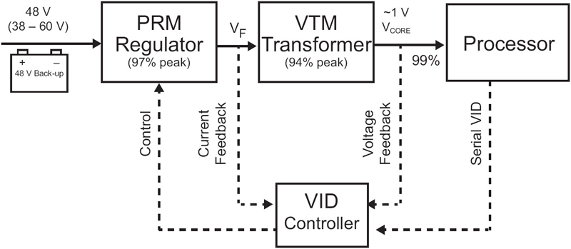
Direct 48 V to VR12.0 implementation For Intel processor systems, the VI Chips form a pure powertrain accompanied by a separate VID controller (figure 3). VID controller acts as a translator between the processor's digital VID and the FPA powertrain, which, in turn, uses the optimal fast analog-control loop to provide an accurate processor core voltage, VCORE. To demonstrate VR12.0 compliance, Vicor engineers created a voltage-regulator-test board configured to support a 145-W, socket-R processor. A VTT (voltage-test tool), inserted into the processor socket, emulates processor behavior to characterize the performance of the powertrain. Monitoring instrumentation records the performance and compares it to the VR12.0 specifications using an automated spreadsheet.
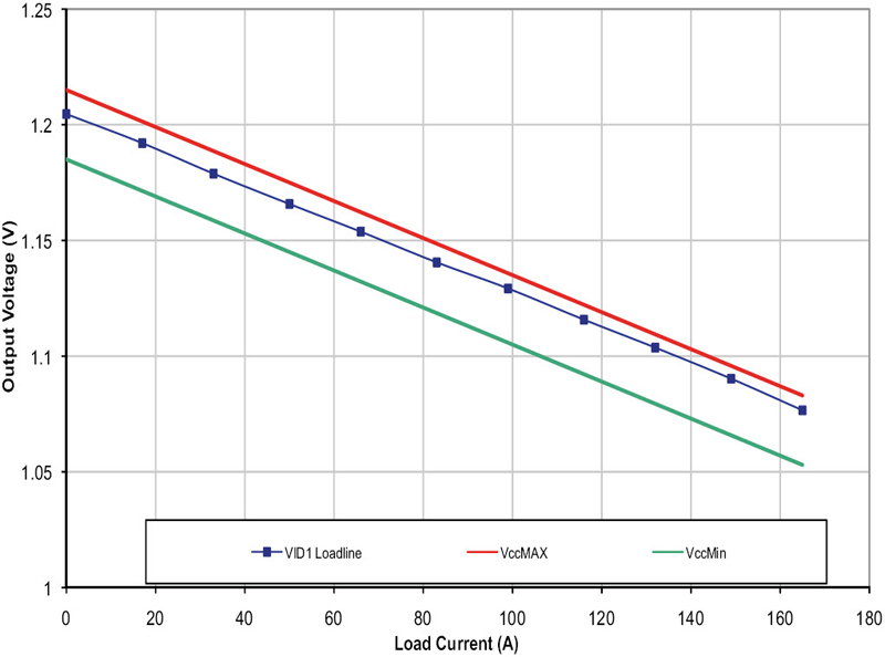
As processor-current demand increases, the power subsystem cannot respond instantly, so the VR12.0 standard allows VCORE to droop in relation to the load. A plot of VCORE versus processor current is known as a load line. The standard requires that the system design maintains the VCORE load line within tight limits to ensure processor stability and performance (figure 4). Under load transients (16 to 147 A) the FPA system has a clean, stable response within 5 μs with only SMT ceramic caps. The FPA system does not use traditional large, unreliable electrolytic capacitors.
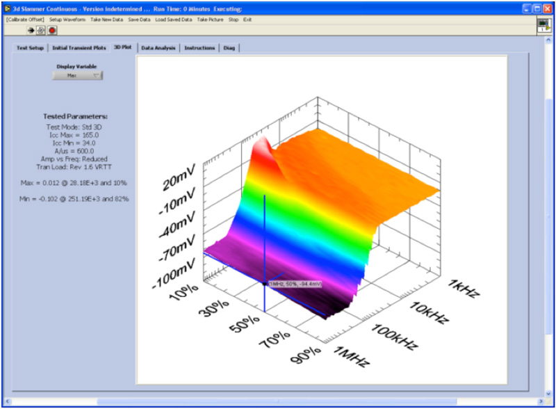
The core voltage response to a VID instruction—Dvid_ps0_121A_up (1.05 V to 1.07 V) —shows that the FTP reacts with a stable output in only 2 μs. Additional, more stringent tests, using sweeps of processor frequency, load power, and VID commands provide 3D-matrix plots (figure 5).
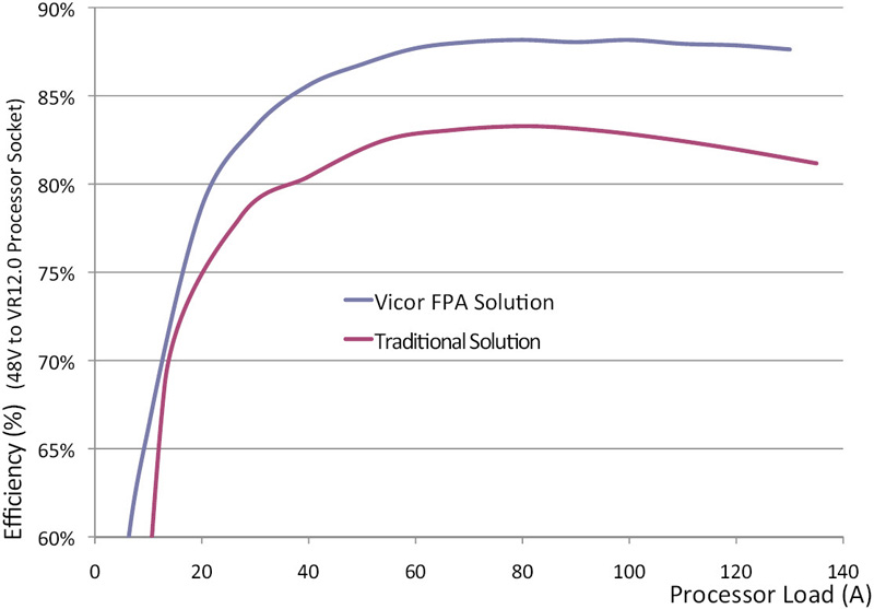
Savings A complete evaluation of the powertrains showed significant size and efficiency savings for FPA versus the traditional IBA system. Server motherboard real estate (PCB area) is expensive. A reduction in powertrain size means an increase in space available for more compute functionality (processors, memory, and input and output functions). The FPA architecture uses 50% less motherboard than IBA, while eliminating the off -board DC-DC converter—in total, a 2/3 reduction in size. In power terms, the FPA architecture is > 5% more efficient from 60% to 100% processor load (figure6). This is a significant improvement in VR12.0 systems, representing a 10 W or 30% reduction in power loss per processor. Adjusting for 85% usage rate and air-conditioning costs (+70%), the final value per processor is 14.5 W saved. A new-build datacenter typically uses 30,000 processors. Using a $0.13 per kWh price for electricity, 14.5 W quickly becomes $500,000 reduction per year in datacenter operating costs (equivalent to 2,300 imported barrels of oil). The annual saving means that in less than three years, the VI Chip VR12.0 powertrain completely pays for itself. Vicor