Author:
Roland Buerger, DANISENSE A/S
Date
09/01/2023
 PDF
PDF
Click image to enlarge
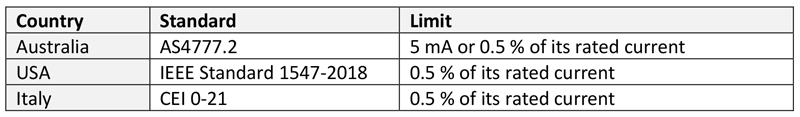
Table 1: DC limits in national standards
In recent years, power quality measurements have been carried out more and more frequently in the electric power and energy industry and on distribution and transport grids. These measurements focus primarily on the classic characteristic parameters such as voltage dips, voltage transients and harmonics. Maximum values are provided by the standards for the quality of distribution networks.
In addition, the compatibility between distribution networks and products can be evaluated according to the standards IEC 61000-2-2 for public low-voltage networks and IEC 61000-2-4 for low-voltage and medium-voltage industrial installations. An important power quality parameter, which is often not considered nor included in the standards, is the DC offset component.
The following questions have until now often received little attention:
How much DC offset is injected to the grid?
How should the DC components be measured and qualified in a reliable way?
How does the DC component impact the remaining system and what can be done to limit its presence?
DC limits in standardization
In Germany, the DC component can be found in the Technical Installation Guideline (TAR) Low Voltage under point 5.4.4.9 Feeding of direct currents into the low-voltage grid. Here specifically is said:
5.4.4.9 Feeding of direct currents into the low-voltage network
A converter shall not inject more than 0.5 % of its rated current or a maximum of 20 mA (the higher value shall be selected) as direct current.
Note 1: The measurement of direct currents is based on DIN EN 61000-4-7 (VDE 0847-4-7) over 10 fundamental oscillation periods
Note 2: Direct currents can cause corrosion damage to cables and damage to other equipment as well as saturation of transformers and other inductors.
The standard text explicitly lists converters as undesirable DC sources. Maximum values for the DC component are also found in other countries. Three examples are listed in table 1.
DC measurements on converters
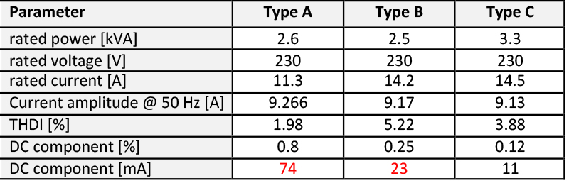
A 2019 IEEE publication examined the DC components of three typical solar inverters. The results are shown in the following table.
Click image to enlarge
Table 2: DC measurements on converters - parameters
Types A and B exceed the limits of 20 mA DC regarding the latest German low voltage directive (TAR).
DC sources in converters
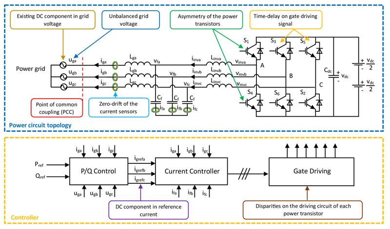
There are several DC sources in converters, as the following figure of a converter system illustrates.
Click image to enlarge
Figure 1: Topology of an LCL-type grid-connected voltage source converter
Unit certificate vs. routine testing
Normatively, the testing of the DC component is already mandatory in the current standards for the unit certificate of generating plants on the low-voltage grid. The DC component measurement is described in IEEE Std 1547.1-2020 under item 5.9.2. In the German prestandard VDE V 0124-100, the test is described under 5.2.6.1.
In general, however, a unit certificate is a type test in which only one unit of the entire series is tested as an example. The root causes for outputting a DC component, could origin from many sources such as build quality or asymmetry of the installed power transistors which may vary slightly from device to device. To know the real DC contribution a routine test on each produced inverter should be reestablished by the inverter manufacturer. Thus, even inverters with an impeccable unit certificate cannot be ruled out as a parasitic DC source when outputting power to the grid.
Measuring equipment for the unit certificate and power quality measurement
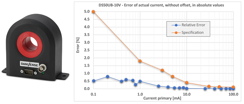
It is a fact that the voltage quality at the grid connection point varies not only from site to site, but also over time. Thus, in the case of poor grid voltage conditions, for example, an already existing DC component can negatively affect the DC current component of the converter. Rogowski coils used in on-site power quality measurements can only detect the AC components in the current signal. Current clamps with Hall element are often not sufficient due to the measurement uncertainty. High-precision fluxgate current transducers from the Danish company Danisense are therefore used in the measurement laboratories of the certification companies. These sensors are calibrated directly in Denmark in the company's own IEC 17025-certified measurement laboratory and are provided with the necessary calibration certificate.
Click image to enlarge
Figure 2: Danisense DS50UB-10V fluxgate transducer with voltage output and accuracy data for low primary currents
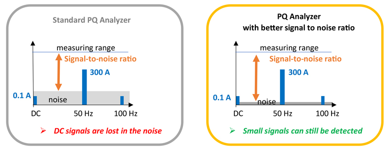
In initial pilot projects, these fluxgate transducers were also used in conjunction with high-precision power quality analyzers. For the demanding measurement of the small DC component in grid connected plants, the Power Quality Analyzer (PQA) should have a very good signal-to-noise ratio, otherwise smaller levels below or above the nominal frequency will be lost in the noise.
Click image to enlarge
Figure 3: PQ analyzers with different signal/noise ratio
At the same time, the PQA should offer a possibility to compensate a possible DC offset of the current sensor, so that even the smallest levels can be measured very accurately. With the power quality analyzer PQA8000H from Neo Messtechnik, the connection of fluxgate transducers is possible. In addition to a very good signal-to-noise ratio, the frequency parameters of the FFT analysis can also be freely selected. The normative grouping according to IEC 61000-4-7 is often too coarse for further analyses, especially in the low-frequency range. For this reason, the PQA can also be used in the high-voltage network to detect geomagnetically induced quasi-direct currents in the range from 0 to 1 Hz.
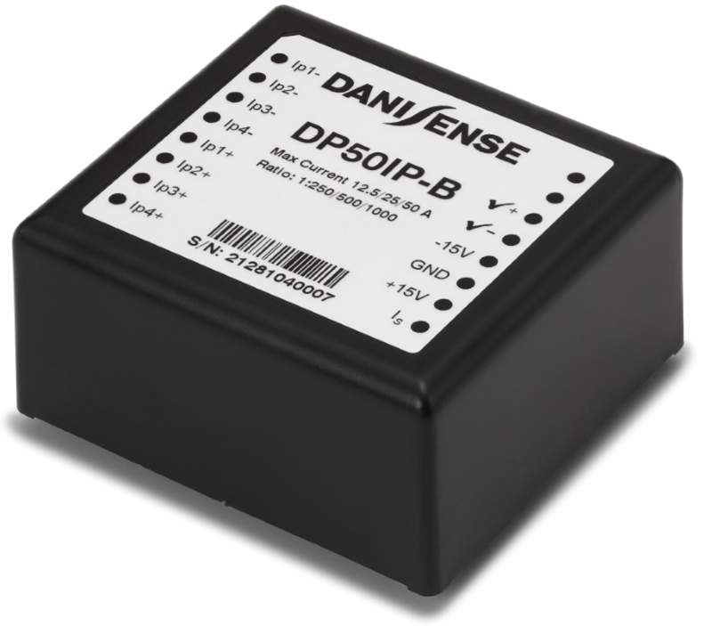
DC measurements with highly accurate fluxgate transducers are also possible directly in the converter. For smaller rated currents, fluxgate transducers are available as PCB mount, so that frequency converters could check the output current themselves.
Click image to enlarge
Figure 4: Danisense DP50IP-B - programmable fluxgate transducer up to 50 A
Plant certificate
If several certified photovoltaic modules and inverters are combined to form a big power plant, a plant certificate is required in addition to the individual unit certificates of the manufacturers. In Germany, a plant certificate is required for all plants larger than 135 kW. The connection point is then often located at the medium voltage level in order to minimize transmission losses. DC measurement is no longer required after the transformer. Nevertheless, a DC current on the low voltage side can significantly reduce the life of the transformer. Thus, DC measurement on the low-voltage side would definitely be in the interest of the plant operator to minimize downtime and maintenance costs of the plant during the entire service life of the transformer.
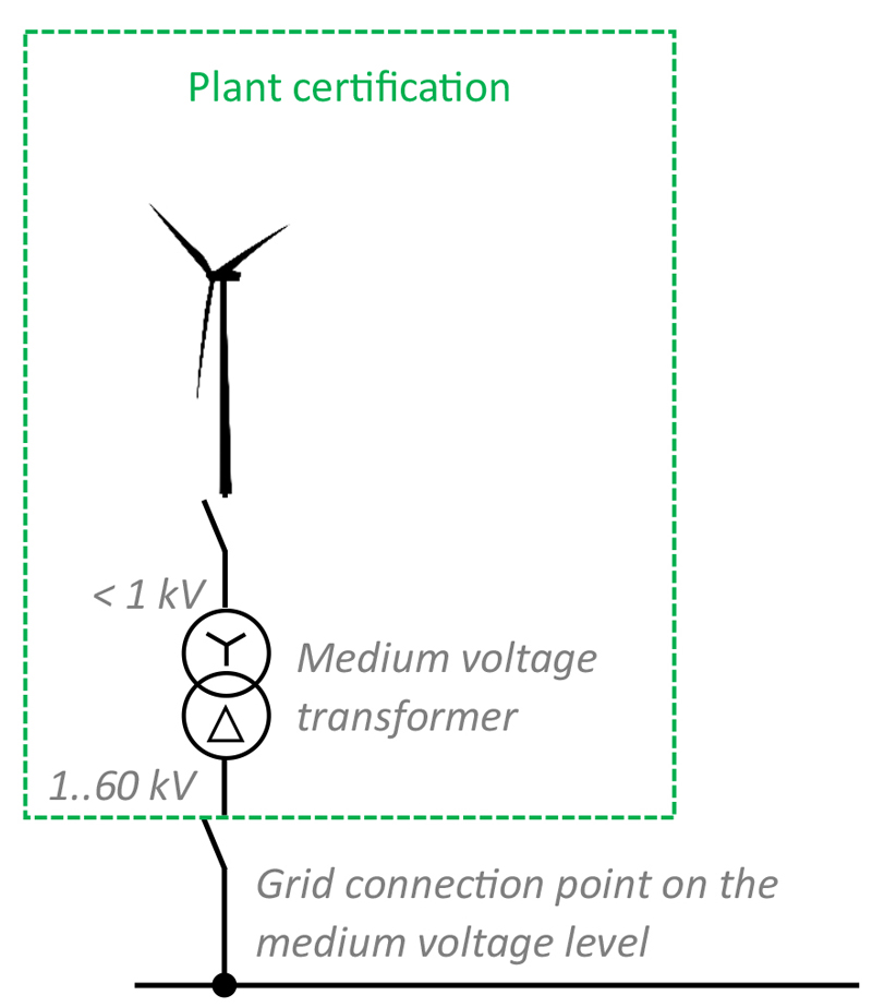
In addition to photovoltaic converters, powerful converters in the wind energy sector can also generate a DC component. DC measurement is no longer required here for plant certification, since the medium-voltage transformer is included in the wind energy plant in most cases which is shown in the following figure.
Click image to enlarge
Figure 5: Plant certificate for a wind turbine with its own medium voltage transformer
Transformer and DC injection
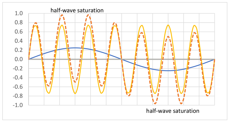
A transformer suffering from unidirectional saturation of the magnetic core generates a higher excitation current, which can lead to core overheating. In addition, vibration, noise, and thermal stress can occur, ultimately shortening the life of the transformer. The following figure shows the half-wave saturation caused by a superimposed low-frequency oscillation.
Click image to enlarge
Figure 6: Half-wave saturation of a transformer
Furthermore, during half-wave saturation, the transformer becomes a non-linear operating device. Here, the magnetic operating range of the transformer is pushed into the saturation range. The linear range of the hysteresis curve is left. As a result, the distortion factor of the voltage signal on the medium-voltage side is increased.
Conclusion
Power converter technologies in renewable energy applications not only suffer from a potential source of harmonics. In recent years, there have been an increasing number of investigation reports made, indicating that DC injection also occurs in many cases.[1] In addition to inverters, non-linear loads can also generate a DC component. Inductive equipment such as motors and transformers are not designed to handle these loads. Despite some efforts from the converter manufacturers’ side to minimize the DC components, a non-negligible DC component is often and increasingly being detected during power quality measurements in the low-voltage network when AC/DC sensors are used.
Click image to enlarge
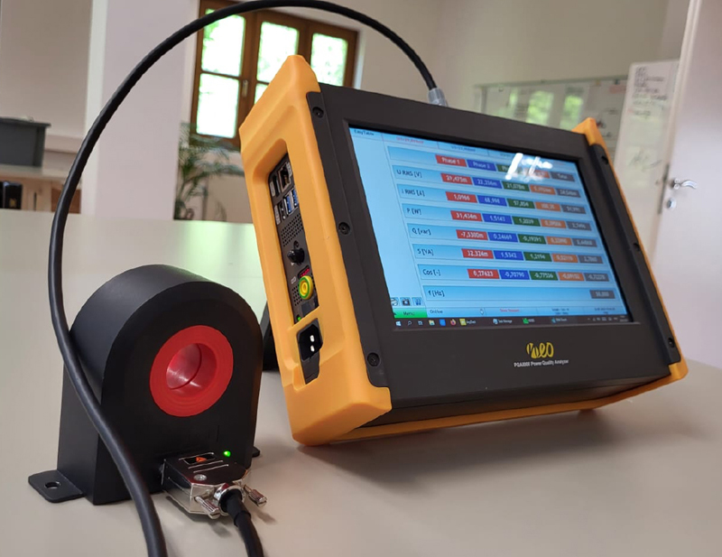
Figure 7: Danisense fluxgate current transducer in combination with the PQA8000 from Neo Messtechnik
Reliable, high performance current sensors and very good PQAs are a basic requirement for the success of this demanding measurement.
[1] Salas, Vicente & Olías, Emilio & Alonso Abella, Miguel & Chenlo, F. & Barrado, A.. (2006). DC Current Injection into the Network from PV Grid Inverters. 2. 2371 - 2374. 10.1109/WCPEC.2006.279668.