Gathering data about other vehicles, the surroundings, and the road
Driverless vehicles require sensors to be able to provide distance readings in relation to a vehicle ahead, behind or to the side to a central controller. Radar, laser, infrared and optical cameras, and ultrasound can all be used to gather data about other vehicles, the surroundings, and the road. Cameras are already used to detect markings on the road to keep a vehicle in the correct lane and provide lane-departure warnings in Advanced Driver Assistance Systems (ADAS). Radar is also used in today’s ADAS for collision detection warnings and adaptive cruise control where a vehicle can follow the car in front.
For example, Infineon Technologies provides the BGT24M 24GHz radar sensor which can be used with an external microcontroller in an electronic control unit (ECU) to modify the throttle to maintain a constant distance from the car in front with a range of up to 20 meters.
A pulse-Doppler approach is used in many automotive radar systems. With this method, the transmitter operates for a short period, known as the pulse repetition interval (PRI), then the system switches to receive mode until the next transmit pulse. The radar reflections are processed coherently to extract range and relative motion of detected objects.
Continuous wave frequency modulation (CWFM) is another approach to use. This method uses a continuous carrier frequency that varies over time with a receiver on constantly. Separate transmit and receive antennas have to be used to prevent the transmit signal from leaking into the receiver.
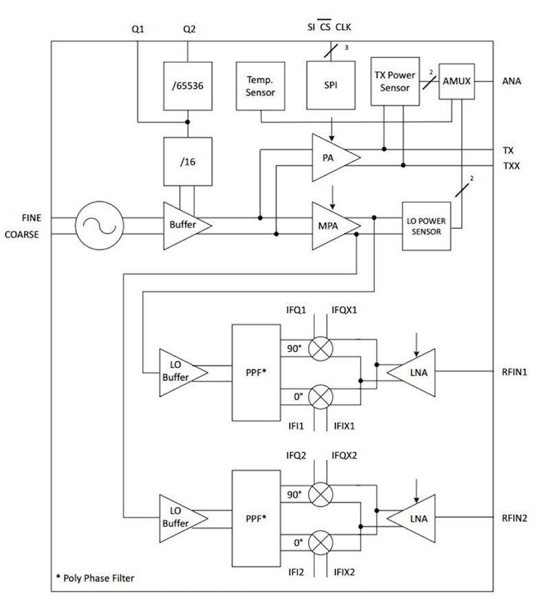
The BGT24MTR12 is a Silicon Germanium (SiGe) sensor for signal generation and reception, operating from 24.0 to 24.25 GHz. This device uses a 24 GHz fundamental voltage controlled oscillator and includes a switchable frequency prescaler with output frequencies of 1.5 GHz and 23 kHz. An RC polyphase filter (PPF) is used for LO quadrature phase generation for the down conversion mixer, while an output power sensor and a temperature sensor are integrated into the device for monitoring (see Figure 1).
Click image to enlarge
Figure 1: The BGT24MTR12 radar sensor from Infineon Technologies (Courtesy of Infineon Technologies)
The device control is via SPI and is manufactured in a 0.18 µm SiGe:C technology offering a cutoff frequency of 200 GHz and packaged in a 32-pin leadless VQFN package.
Driverless vehicle architecture is changing however. Instead of the use of a local ECU, the data from the various radar systems around the vehicle are input into a central high performance controller that combines the signals with those coming from cameras and perhaps from Lidar laser sensors.
This controller can be a high performance general-purpose processor with graphic control units (GCUs), or a field programmable gate array (FPGA) where the signal processing can be handled by dedicated hardware. The result is more emphasis is placed on the analog front-end (AFE) interface devices that have to handle higher data rates and more data sources.
Sensors also changing
The type of radar sensor being used is also changing with 77 GHz sensors providing both longer range and higher resolution. A 77 GHz or 79 GHz radar sensor can be adapted in real time to provide long range sensing of up to 200 meters in a 10° arc (e.g., detecting other vehicles). It can also be used in a wider, 30° sensing arc with a lower range of 30 meters. The higher frequency gives higher resolution which allows the radar sensor system to distinguish between multiple objects in real time, for example detecting a number of pedestrians within that 30° arc. This gives the controller for driverless vehicles more time and more data.
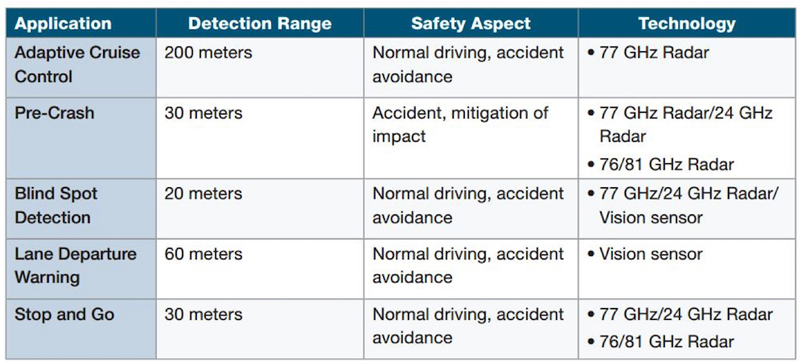
The 77 GHz sensors use silicon germanium bipolar transistors with an oscillation frequency of 300 GHz. This allows one radar sensor to be used for multiple safety systems such as headway alert, collision warning and automatic braking (see Figure 2). The 77 GHz technology is also more resistant to the vibration in the vehicle resulting in less filtering being required.
Click image to enlarge
Figure 2: The different use cases, by NXP, for radar sensors in driverless vehicles (Courtesy of NXP Semiconductors)
The sensors are used by the vehicle coordinate system (VCS) to detect the range, speed and azimuth of a target vehicle. The data accuracy depends on the precise alignment of the radar sensor. A radar sensor alignment algorithm executes at more than 40 Hz continuously while the vehicle is running. In 1 ms, calculation of the misalignment angle based on data provided by the radar sensor, as well as the vehicle speed, the sensor’s position on the vehicle, and its pointing angle must be performed.
Recorded sensor data captured from road testing a real vehicle can be analyzed by software tools. This test data can then be used to develop a radar sensor alignment algorithm that calculates sensor misalignment angles from raw radar detection and host vehicle speed using a least squares algorithm. Additionally, this also estimates the computed angle’s accuracy based on the residual of the least squares solution.
System architecture
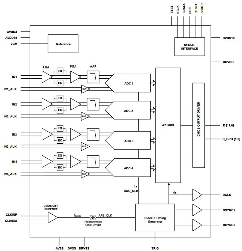
An analog front end such as the AFE5401-Q1 from Texas Instruments (see Figure 3) can be used to link the radar sensor to the rest of the automotive system. This device includes four channels, with each channel comprising a low-noise amplifier (LNA), an optional equalizer (EQ), a programmable gain amplifier (PGA), and an anti-alias filter followed by a high-speed, 12-bit, analog-to-digital converter (ADC) at 25 MSPS per channel. The four ADC outputs are multiplexed on a 12-bit, parallel, CMOS-compatible output bus.
Click image to enlarge
Figure 3: The four channels in the AFE5401 radar analog front end from Texas Instruments can be used for multiple sensors (Courtesy of Texas Instruments)
For a lower cost system, the AD8284 from Analog Devices provides an analog front end with a four channel differential multiplexer (mux) that feeds a single channel low noise preamplifier with a PGA and an antialiasing filter (AAF). This device also uses a single direct-to-ADC channel, all integrated with a single, 12-bit ADC. Additionally, the AD8284 incorporates a saturation detection circuit for high frequency overvoltage conditions that would otherwise be filtered by the AAF. The analog channel features a gain range of 17 dB to 35 dB in 6 dB increments and an ADC with a conversion rate of up to 60 MSPS. The combined input referred voltage noise of the entire channel is 3.5 nV/√Hz at maximum gain.
The output of the AFE is then fed into a processor or an FPGA such as the IGLOO2 or Fusion from Microsemi or Cyclone IV from Altera. One of these devices can implement the 2D fast Fourier transform (FFT) in hardware using the FPGA design tools to handle the FFT and provide the required data on surrounding objects. This data can then be fed into a central controller.
A critical challenge for the FPGA is the detection of multiple objects.
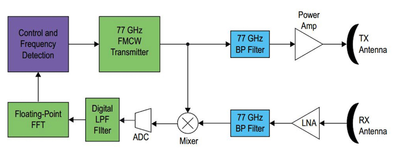
This is more complicated for CWFM architectures than pulse-Doppler. One way to do this is to vary the duration and frequency of the ramps and evaluating how the detected frequencies move in the spectrum with different steepness of frequency ramps. Since the ramp can be varied at 1 ms intervals, hundreds of variations can be analyzed per second (see Figure 4).
Click image to enlarge
Figure 4: The CWFM radar front end used with an FPGA (Courtesy of the Altera division of Intel)
The data fusion from other sensors can also help in the detection of multiple objects, as camera data can be used to discriminate between stronger returns from vehicles compared to weaker returns from people, and what sort of Doppler offset to expect. Another option is to use multimode radar that uses CWFM to find targets at longer range on the highway, and short-range pulse-Doppler radar for urban areas where pedestrians are more likely.
Looking forward
ADAS sensor system evolution for driverless vehicles is changing the way radar systems are being implemented. Moving from the simpler collision avoidance or adaptive cruise control to all around detection is proving to be a significant challenge. Radar is a leading technology for this sensing technique since it is well established with automotive manufacturers.
Bringing together sensors with multi-mode CWFM and pulse-Doppler architectures at a higher 77 GHz frequency, along with data from other sensors such as cameras is also presenting processing sub-systems with a significant challenge. Essential to the continuing development of autonomous vehicles is solving these challenges in a safe, consistent and cost effective way.