Pulse Frequency Modulation High-Brightness LED power driver
Increasingly, with the development and refurbishment of Power Grid systems, more efficient street and public lighting systems are becoming ever higher on a government's agenda. Over the last years, the significant improvements in the field of solid-state lighting technology have been paving the way for the possibility of replacing conventional light sources (such as halogen and fluorescent lamps) with high-brightness LEDs (HBLEDs). They offer significant advantages; extremely long lifetime, low maintenance, robustness, low-voltage operation and good colour-rendering properties. The main barrier to universal adoption is the cost of a complete LED light system, which includes the LED itself and the auxiliary control circuitry. This justifies the efforts of the research institutes and the industry in improving the overall system efficiency so that the energy and maintenance cost savings can cover up the installation expenses. It is well-known that the LED emission intensity increases linearly with increasing small forward currents. On the other hand, for high forward currents, the emission intensity deviates from this linear behaviour and shows a tendency to saturate. Recently, the two commonly used driving solutions for LEDs are the analog and the pulse width modulation (PWM)/dimming techniques. The former stems from a simple concept that is the direct regulation of the forward current. The latter is carried out by switching on and off the LEDs repeatedly while the LED string current, during its on-phase, is forced to its nominal value. The so-called dimming frequency is usually set so that the dimming effect is not critical to the human perception. That said, it is often discussed in the literature that, due to the above-mentioned nonlinearity, the efficacy of the LEDs driven by a PWM will be lower than that driven by dc for the same average current, since a larger current amplitude exists in the average-equivalent PWM case. In other words, the light output obtained from a LED is strongly dependent on the actual current flowing through it.
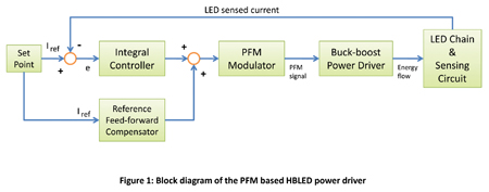
The control solution proposed here is focused on the LED efficiency rather than on the auxiliary control circuitry. The underlying principle of the proposed solution is to set and to regulate the LED dc current value by means of a driving circuit based on Pulse Frequency Modulation (PFM). A block diagram of the proposed circuit is shown in Figure 1 and is made up of:
- The controller
- PFM based actuator
- Buck-boost power driver
- The plant, i.e. the LED chain
Unlike PWM, in which the width of square pulses is varied at constant frequency, PFM is accomplished by using fixed-duration pulses and varying the repetition rate. The controller determines the frequency of the PFM. The controller is essentially based on the combined action of a feed-back error integral control and a reference feed-forward control. The error is calculated by subtracting the LED current reference from the measured LED current. From control theory it is well-known that, thanks to the integral action, the reference steady-state error can be eliminated, although this comes at the expense of deterioration in the dynamic response. The purpose of the reference feed-forward compensator is just to make up for the delay induced by the integral action. The output of the controller regulates the frequency of the PFM pulse train, and then the flow of energy driven by the buck-boost power driver towards the LEDs. An accurate choice of the circuit parameters can guarantee an acceptable current ripple value.
Figure 2 shows the electrical scheme of the PFM based high brightness LED power driver with the design details of the afore-mentioned blocks.

A DC/DC buck-boost converter with an output capacitor is used. It has cyclic changes in topology due to the switching action of the semiconductor devices. During a cycle of operation, the main power switch (driven in our case by the PFM actuator output) is turned on and off. When the switch is closed:
- the inductor receives energy from the source and is charged up
- the diode is in the reverse region (that is, it is an open circuit)
- the capacitor is discharged into the output load (i.e., the LEDs) and the LED current decreases.
- the inductor maintains the current flow in the same direction and the diode is forward-biased
- the inductor transfers the accumulated energy into the capacitor and, as soon as the LED forward drop voltage is reached, into the LEDs as well
- the output voltage/current rises.
- the LED current flows in continuous mode thus guaranteeing a better efficiency for what concerns the LED emission intensity
- the current set point is reached, showing also an acceptable ripple
- the frequency of the PFM actuator (not shown in the figures) is lower during the transients
- the reference feed-forward compensator reduces quite considerably the transient duration.


With the increase in efficiency and subsequent low maintenance that can be achieved with advanced driving system concepts, power utilities can justify the initial start-up costs associated with HBLED lighting systems, to use energy more wisely and to gain the advantages of lifetime cost for indoor as well as outdoor applications. In this article, an ad-hoc solution based on a Pulse Frequency Modulation power driver is presented. Its main idea is to set and regulate the LED dc current to a specific analog value. By doing so, a higher level in terms of LED efficiency can be reached since this technique deals with the nonlinearity behavior of the LED emission intensity with the related forward current. www.grace.ing.unisannio.it