Author:
Bosheng Sun, System Engineer, Texas Instruments
Date
12/03/2014
 PDF
PDF
PFC (power-factor correction) circuit designers have used average current-mode control for decades (figure 1). Various analog PFC-control chips based on this control algorithm are available in the commercial market.

Clcik image to enlarge
Figure 1: Average-current-mode control for PFC
The performance of average current-mode control often is considered adequate for most commercial power applications with 50 or 60 Hz AC line input. However, the traditional average current-mode control causes the inductor current to lead the input voltage, resulting in a non-unity fundamental displacement power factor and zero-crossing distortion. This situation gets worse with PFC operating in a high-frequency AC environment, such as 400 Hz, often used in airborne systems. The high input-current quality required in these systems is difficult to achieve through traditional control methods. A new control method, called DFF control, effectively can reduce input-current distortion under high line frequencies (references 1, 2, and 3).
Duty-ratio feedforward control
The basic idea of DFF control is to pre-calculate a duty ratio to alleviate the feedback controller of the task. For the boost topology operating in continuous conduction mode, the duty-ratio, dFF, is:
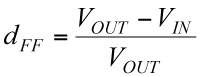
This duty-ratio pattern effectively produces a voltage across the switch, the average of which, over a switching cycle, is equal to the rectified input voltage. A regular current loop compensator changes the duty ratio around this calculated duty-ratio pattern. Since the impedance of the boost inductor at the line frequency is low, a small variation of the duty ratio produces enough voltage across the inductor to generate the required sinusoidal current waveform (figure 2).
Click image to enlarge
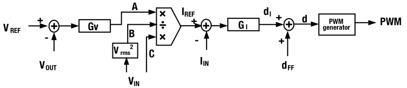
Figure 2: Duty-ratio feedforward control for PFC
The feedforward duty ratio, dFF calculated in Equation 1 adds to the traditional average current-mode control output, dI. The circuit uses the final duty ratio, d, to generate a PWM waveform to control PFC.
Digital implementation
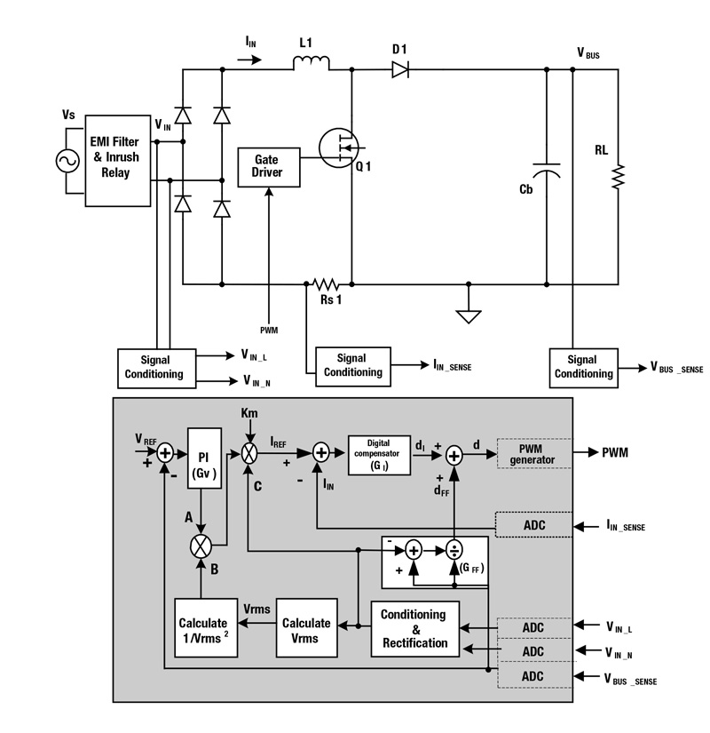
Figure 3 is a block diagram of the digital implementation of this DFF control for a single-phase PFC. A signal conditioning block senses the input voltage, VIN, before the bridge rectifier. The block senses the line and neutral separately by two ADC channels. They are then rectified by firmware to get rectified VIN. Another ADC channel senses the PFC output voltage, VOUT. A resistive shunt senses the current signal and its feedback signal IIN_SENSE serves as an input for current loop control. Note the use of three controllers: Voltage loop GV, traditional average current-mode GI, and a DFF GFF.
Click image to enlarge
Figure 3: Duty-ratio feedforword control digital implementation
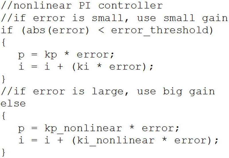
The voltage loop controller, GV, can be quite simple. The controller compares the VOUT measurement with a reference. The error goes to a pure firmware PI (proportional-integral) controller. Its output, depicted as A in Figure 3, is used for current reference calculations. To meet the transient-response requirement, a nonlinear PI controller is necessary. Listing 1 is an example of a firmware nonlinear PI controller.
The traditional average current-mode controller GI regulates the inductor current so that the input current follows the input voltage. To do this, first calculate the current reference. For an average current-mode controlled PFC, calculate the current reference as:

where Km is the multiplier gain, A is the voltage loop output, B = 1/Vrms2, and C is input voltage, VIN.
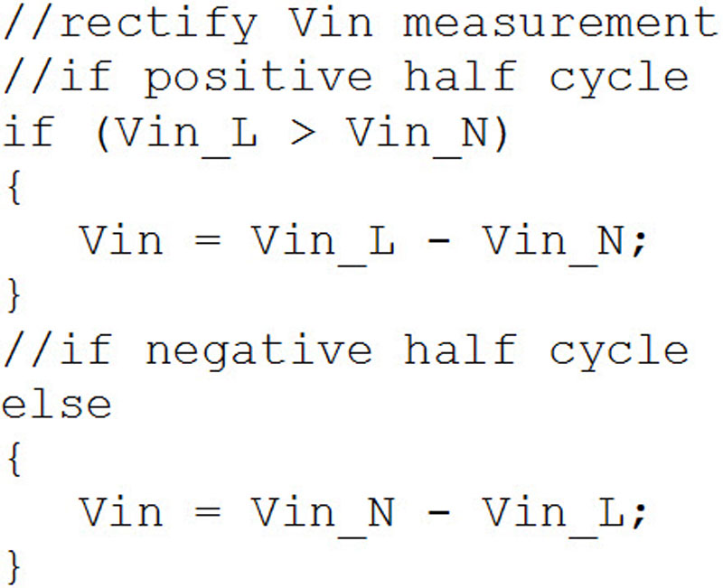
The circuit measures the components of VIN—line and neutral—separately by two ADC channels. Firmware then rectifies the digital representation of the waveform (listing 2).
By definition, the RMS value is:
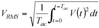
which in discrete form is:
The sampled VIN is squared and accumulated in each AC cycle, then divided by the number of samples to get VRMS2.
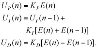
Once the system calculates the current reference, it compares that value to the current feedback signal. The digital error information passes to a digital compensator for current loop compensation. The digital compensator could be firmware- or hardware-based, a traditional PID (proportional-integral-derivative), or a two-pole two-zero structure.
A discrete-time implementation of a PID controller calculates the three terms:
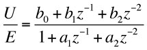
An example of a discrete-time two-pole two-zero controller expression is:
A regular average current-mode control uses its output, dI, to generate a PWM pulse to control PFC. However, a DFF control only uses that output to compensate for the difference between the current reference and the real inductor current generated by DFF. The DFF controller GFF uses equation 1. Firmware adds dFF with dI to get the final duty term d. The final duty term, d, goes into a PWM module to generate the corresponding PWM pulse.
Enhanced duty-ratio forward control
A DFF controller calculates dFF based on VIN and VOUT, then adds dI to get the final value for d. All these calculations execute in firmware so the CPU’s speed determines the control-loop speed, which then affects the loop bandwidth. A faster CPU can achieve a higher bandwidth. However, the faster CPU is also more expensive and dissipates demands more power.
Given a low-cost digital controller with a clock frequency of 30 MHz, a 50-kHz interrupt loop can implement the current-loop control. This includes ADC measurements, VRMS calculation, current-reference generation, and duty-ratio calculation. All these tasks need to execute in 20 μs. Further increasing the interrupt-loop speed causes it to overflow. With this setting, the current-control loop is running at a speed of 50 kHz. The bandwidth normally is less than one-tenth of the control loop speed. Thus, the bandwidth is less than 5 kHz, which is relatively low for PFC current regulation.
Referring again to figure 3, although the CPU calculates IREF and dFF at 50 kHz, the digital compensator and PWM generator are hardware, so they can run at a much faster speed, for example, 100 kHz. This means that the system can calculate dI at 100 kHz. So it is really the sum dFF + dI = d that slows down the control loop speed. If hardware can implement the dFF + dI = d sum as well, then the whole loop is faster than before, and the bandwidth is improved.
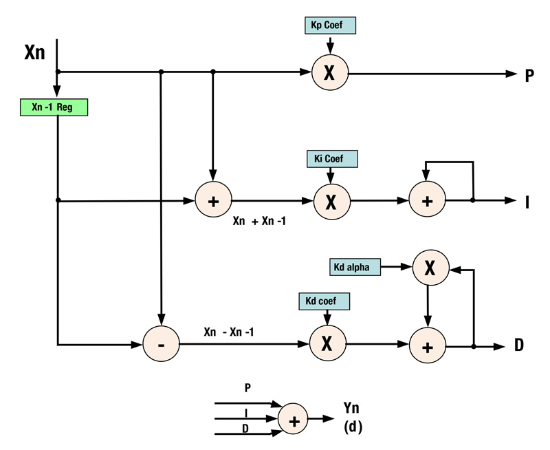
This is possible with second-generation digital power controllers such as the Texas Instruments UCD3138. The digital compensator in this device is a traditional PID structure with an extra alpha to provide two-pole, two-zero compensation (figure 4). P, I and D are three separate branches. Their outputs add to generate a final control signal. Since PFC current loop is a first order system, normally a PI controller is enough for the compensation. This leaves the D branch spare, which could be used to improve the DFF control speed.
Click image to enlarge
Figure 4: A second-generation digital-power-controller PID structure, based on the UCD3138
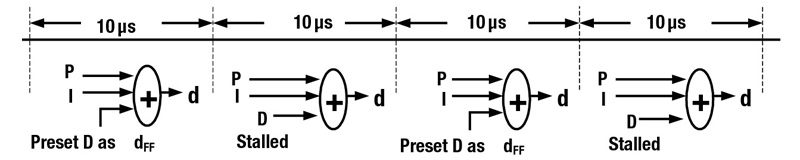
The D branch has two advanced features. First, its output can be set to a predefined value. Second, it’s output can be stalled or frozen at its current value. With these two features, we can still calculate dFF every 20 μs, then preset the D branch output at this dFF, then stall it. Although dFF is calculated at 50 kHz, the P, I, and d = P + I + dFF is running at 100 kHz, and the PWM output updates at 100 kHz. So the effective control loop is running at 100 kHz, double the loop speed before (figure 5). With this faster control loop speed, the bandwidth can push higher and, consequently, THD and PF improve.
Click image to enlarge
Figure 5: Enhanced duty-ratio feedforward structure
Experimental results
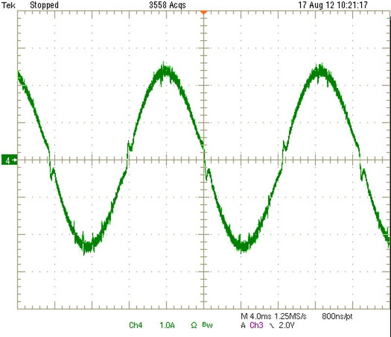
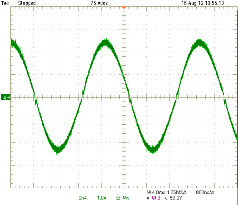
Texas Instruments engineers tested the DFF and its enhanced version on a 360-W single-phase PFC. Waveforms from these two different controllers, operating under the same test conditions, show that the enhanced DFF control makes the AC current waveform much smoother and improve THD from 4.04% to 1.9% (figures 6 and 7). Table 1 shows the THD and PF difference under these two controls.
Click image to enlarge
Figure 6: Line current with DFF control: VIN = 110 V, load = 180 W, THD = 4.04%, PF = 1
Click image to enlarge
Figure 7: Line current with enhanced DFF control: VIN = 110 V, load = 180 W, THD = 1.9%, PF = 1
Click image to enlarge
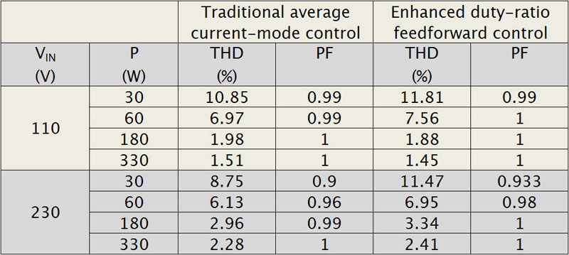
Table 1: THD and PF comparison between average current-mode control and enhanced DFF
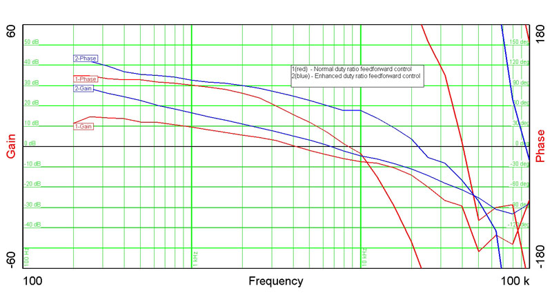
The improvement results from the increased bandwidth with enhanced DFF control. Figure 8 shows the bode plots for these two cases. For a fair comparison, the PID control gains are set to be the same. With the enhanced DFF, the bandwidth increases from 4.3 to 8.5 kHz, and phase margin increases from 25° to 50°.
Click image to enlarge
Figure 8: Bode plot comparison between a normal DFF and an enhanced DFF
DFF and average current-mode comparison
It is interesting to see the difference between this enhanced DFF control and a traditional average current-mode control. For a fair comparison, TI engineers tested these two control methods with the same PFC unit and the same PID gain for GI. Table 1 shows the THD and PF under these two cases. Note that the DFF control gives better PF, but worse THD. For applications with strict PF requirements, the enhanced DFF is a better choice.
References:
1. Van de Sype, DM, et al, Duty-ratio feedforward for digitally controlled boost PFC converters, IEEE Transactions on Industrial Electronics, vol 52, nbr 1, Feb 2005.
2. Chen, M and J Sun, Feedforward current control of boost single-phase PFC converters, IEEE Transactions on Power Electronics, vol 21, nbr 2, Mar 2006.
3. Prathapan, PT et al, Feedforward current control of boost-derived single-phase PFC converters, APEC vol.3, 2005.