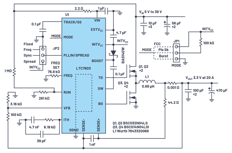
Figure 1: Electrical schematic of an LTC7803-based converter with VIN from 5 V to 38 V and VOUT at 3.3 V at 20 A
LTC7803 isa synchronous step-down controller developed by ADI to simplify the design of high-performance power supplies. The main features of the controller are integrated, low impedance gate drivers able to switch N-channel MOSFETs, which reduce overall converter cost and increases efficiency; extremely low operating quiescent current (5 µA); 40 V wide input/output voltage range; a very high range of programmable switching frequency from 100 kHz up to 3 MHz; sense resistor or DCR sensing for further advance efficiency; and 100% duty cycle. Another feature is Spread Spectrum® operation. LTC7803 modulates the switching frequency in ±15% range, which simplifies EMI compliance and reduces the cost of EMI filters.
Electrical Schematic and Functionality
The electrical schematic of the step-down converter is presented on Figure 1. The converter delivers 3.3 V at 20 A from the input rail, with a range from 5 V to 38 V. The power train includesMOSFETs Q1 through Q4, inductor L1, and input/output filter capacitors. MODE pin and Jumper JP1 define forced continuous conduction, pulse skipping, or Burst Mode® operation. Each mode of operation has advantages and disadvantages. In FCM, low output ripple over the entire range of output currents comes at the expense of efficiency at light loads. Burst Mode provides extremely high efficiency at light loads or no load but gives higher output voltage ripple at light loads.
Another advantage of the LTC7803 is its ability to synchronize to an external clock to avoid interference problems caused by interaction of different frequencies in the host system. Jumper JP2, FREQ SET, allows selection between fixed frequency, synchronization to an external clock or spread frequency operation. Please note, if Burst Mode is selected (MODE pin tied to GND) and synchronization is active (clock pulses on PLLIN/Spread pin), then the controller operates in the FCM. From a practical standpoint, it’s preferable to use pulse skip mode in this situation. Pulse skip mode (MODE pin tied to INTVCC through the 100 kΩ resistor) provides much better efficiency at light loads compared to FCM.
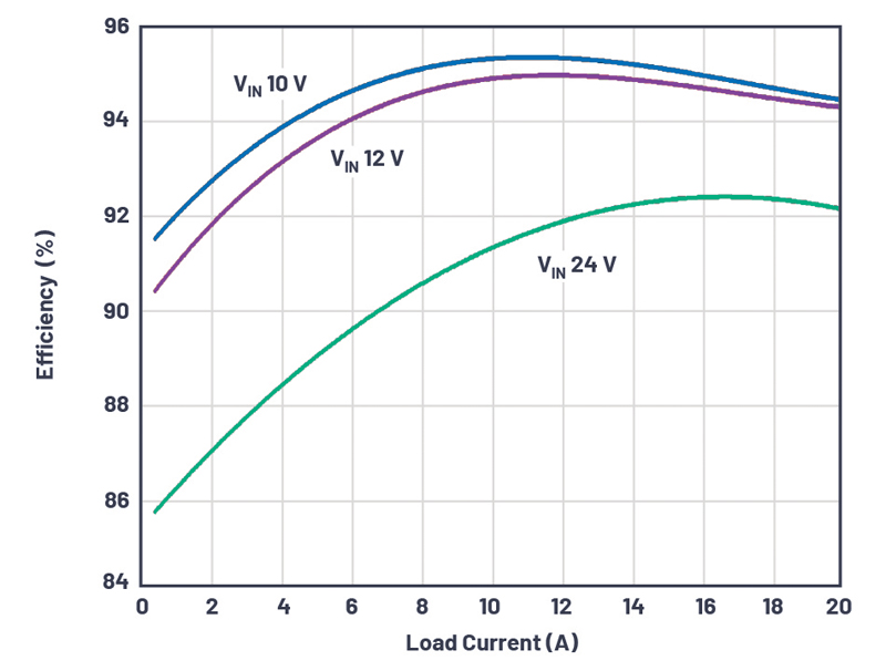
Efficiency and Spread Spectrum Operation
Figure 2 shows the efficiency of the converter in Burst Mode with different input voltages.
Click image to enlarge
Figure 2: Converter efficiency in pulse skip and Burst Mode operation
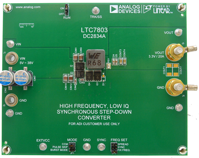
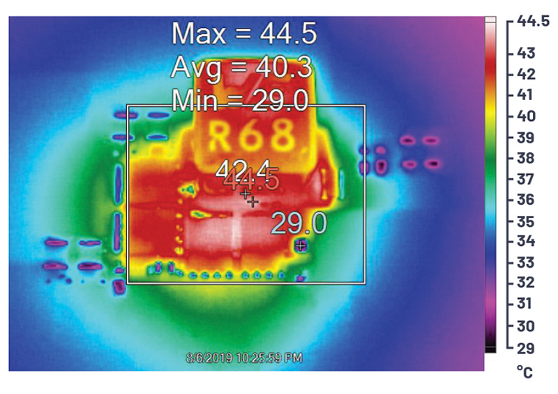
The DC2834A demo board, shown in Figure 3, was used for LTC7803 evaluation. Figure 4 shows a thermal image of the DC2834 at full load.
Click image to enlarge
Figure 3: DC2834A demo board
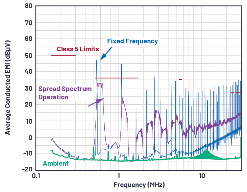
Spread Spectrum operation is a very important advantage of the LTC7803. This feature drastically reduces the radiated and conducted noise of the converter and significantly simplifies system compliance for the whole system to the EMI standards. Figure 5 compares two conducted EMI sweeps with and without Spread Spectrum operation in the CISPR 25 Class 5 limits.
Click image to enlarge
Figure 4: Converter thermal image with VIN 12 V and VOUT 3.3 V at 20 A, from natural convection cooling with no air flow
Click image to enlarge
Figure 5: Conducted EMI sweeps with Spread Spectrum operation enabled and disabled (fixed frequency) in the CISPR 25 Class 5 limits
Conclusion
LTC7803, the low IQ synchronous step-down controller, significantly simplifies the design of highly efficient power converters. It’s able to function in a wide range of input/output voltages with optimal transient response. The LTC7803 provides extremely important features such as Burst Mode and Spread Spectrum operation for further improving efficiency and compliance to EMI standards.